


Chapter 2 Hardware Overview of the NI 78xxR
© National Instruments Corporation 2-7 R Series Intelligent DAQ User Manual
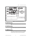
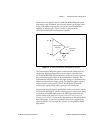
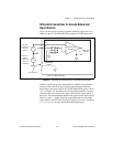
Connection of AI signals to the NI 783xR/784xR/785xR depends on the
input mode of the AI channels you are using and the type of input signal
source. With different input modes, you can use the instrumentation
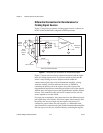
amplifier in different ways. Figure 2-4 shows a diagram of the
NI 783xR/784xR/785xR instrumentation amplifier.
Figure 2-4. NI 783xR/784xR/785xR Instrumentation Amplifier
The instrumentation amplifier applies common-mode voltage rejection
and presents high input impedance to the AI signals connected to the
NI 783xR/784xR/785xR. Input multiplexers on the device route signals to
the positive and negative inputs of the instrumentation amplifier. The
instrumentation amplifier converts two input signals to a signal that is the
difference between the two input signals. The amplifier output voltage is
referenced to the device ground. The NI 783xR/784xR/785xR ADC
measures this output voltage when it performs A/D conversions.
You must reference all signals to ground either at the source device or at the
NI 783xR/784xR/785xR. If you have a floating source, reference the signal
to ground by using RSE input mode or the DIFF input mode with bias
resistors. Refer to the Differential Connections for Nonreferenced or
Floating Signal Sources section of this chapter for more information about
these input modes. If you have a grounded source, do not reference the
signal to AIGND. You can avoid this reference by using DIFF or NRSE
input modes.
+
+
–
–
V
m
= [V
in+
– V
in–
]
V
in+
V
in–
V
m
Instrumentation
Amplifier
Measured
Voltage