


Chapter 2 Hardware Overview of the NI 78xxR
© National Instruments Corporation 2-17 R Series Intelligent DAQ User Manual
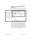
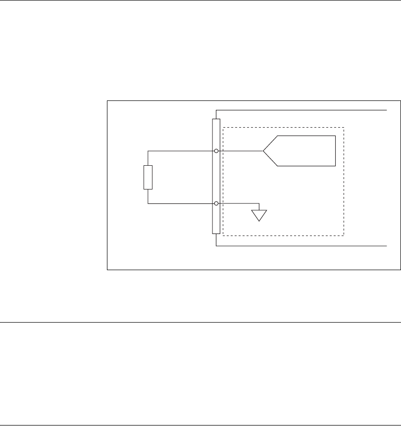
Connecting Analog Output Signals
The AO signals are AO <0..n> and AOGND.
AO <0..n> are the AO channels. AOGND is the ground reference signal for
the AO channels.
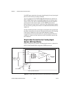
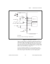
Figure 2-10 shows how to make AO connections to the
NI 783xR/784xR/785xR.
Figure 2-10. Analog Output Connections
Digital I/O
You can configure the NI 78xxR DIO lines individually for either input or
output. When the system powers on, the DIO lines are at high impedance.
To set another power-on state, you can configure the NI 78xxR to load a VI
when the system powers on. The VI can then set the DIO lines to any
power-on state.
Connecting Digital I/O Signals
The DIO signals on the NI 78xxR RDIO connectors are DGND and
DIO<0..39>. The DIO signals on the NI 783xR/784xR/785xR RMIO
connector are DGND and DIO<0..15>. The DIO<0..n> signals make up the
DIO port and DGND is the ground reference signal for the DIO port. The
NI 781xR has four RDIO connectors for a total of 160 DIO lines. The
Load
VOUT 0
+
–
AOGND0
NI 783xR/784xR/785xR
AO0
Channel 0