


Appendix A Connecting I/O Signals
© National Instruments Corporation A-5 R Series Intelligent DAQ User Manual
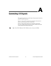
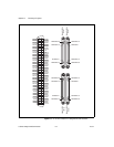
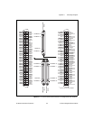
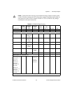
Caution Connections that exceed any of the maximum ratings of input or output signals
on the NI 78xxR can damage the NI 78xxR and the computer. Maximum input ratings for
each signal are in the Protection column of Table A-2. NI is not liable for any damage
resulting from such signal connections
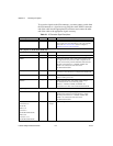
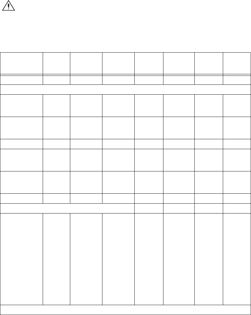
Table A-2. NI 78xxR I/O Signal Summary
Signal Name
Signal
Type and
Direction
Impedance
Input/
Output
Protection
(Volts)
On/Off
Source
(mA at V)
Sink
(mA at V)
Rise Time Bias
+5V DO — — — — — —
Analog Signals (NI 783xR/784xR/785xR Only)
AI<0..7>+ AI 10 GΩ in
parallel with
100 pF
42/35 — — — ±2 nA
AI<0..7>– AI 10 GΩ in
parallel with
100 pF
42/35 — — — ±2 nA
AIGND AO — — — — — —
AISENSE AI 10 GΩ in
parallel with
100 pF
42/35 — — — ±2 nA
AO<0..7> AO 1.25 Ω Short
circuit to
ground
2.5 at 10 2.5 at –10 10 V/μs —
AOGND AO — — — — — —
Digital Signals (All NI 78xxR Devices) — — — —
DIO<0..39>
Connector<0..3>
(NI 781xR)
DIO<0..15>
Connector 0
(NI 783xR,
NI 784xR, and
NI 785xR)
DIO<0..39>
Connector <1..2>
(NI 783xR,
NI 784xR, and
NI 785xR)
DIO — –0.5 to +7.0
(NI 783xR)
–20 to 20
(NI 784xR/
NI 785xR)
4.0 at 2.4 4.0 at 0.4 — —
AI = Analog Input AO = Analog Output DIO = Digital Input/Output DO = Digital Output