


Chapter 2 Hardware Overview of the NI 78xxR
© National Instruments Corporation 2-19 R Series Intelligent DAQ User Manual
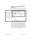
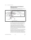
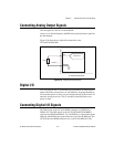
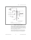
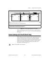
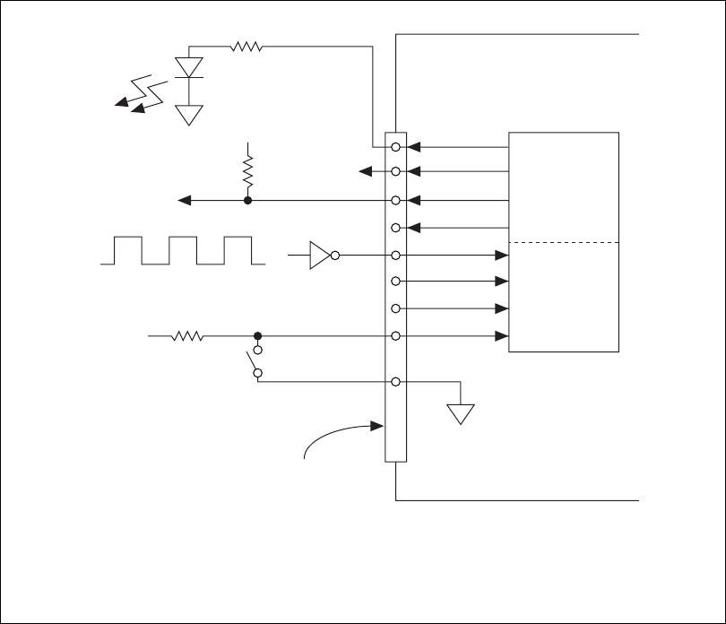
Figure 2-11. Example Digital I/O Connections
Figure 2-11 shows DIO<0..3> configured for digital input and DIO<4..7>
configured for digital output. Digital input applications include receiving
TTL, LVTTL, CMOS, or LVCMOS signals and sensing external device
states, such as the state of the switch shown in Figure 2-11. Digital output
applications include sending TTL or LVCMOS signals and driving external
devices, such as the LED shown in Figure 2-11.
The NI 78xxR SHC68-68-RDIO cable contains individually shielded
bundles that route each digital signal on an individually shielded pair of
wires, and each signal is twisted with its own wire to digital ground.
*
3.3 V CMOS
†
Use a pull-up resistor when driving 5 V CMOS devices.
LED
TTL, LVTTL, CMOS, or LVCMOS Signal
+5 V
Switch
I/O Connector
DGND
NI 783xR/784xR/785xR
DIO<0..3>
DIO<4..7>
+5 V
5 V CMOS
†
TTL or
LVCMOS
*
Compatible
Devices
DGND