


Chapter 2 Installation and Configuration
© National Instruments Corporation 2-11 NI 8171 Series User Manual
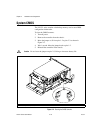
Using the Controllers with PXI-1020 and
PXI-1025 Chassis
The NI 8176 and NI 8175 controllers interface directly to the National
Instruments PXI-1020 and PXI-1025 chassis. The interface contains
signals to interface to the chassis LCD display, IDE CDROM drive,
and PS2 mouse and keyboard.
LCD Display
To enable/disable the LCD display for a PXI-1020 or PXI-1025 chassis:
1. Install the controller in a PXI-1020 or PXI-1025 chassis.
2. Connect a CRT monitor to the VGA connector on the NI 8171 series
controller.
3. Power on the chassis and enter the BIOS setup program during the
boot. (When the message Press <DEL> to enter SETUP appears,
press <Delete> or <Del> on the numeric keypad. The message
Entering Setup… appears, and the setup program is loaded after a
short delay.)
4. In the PXI Setup menu, set the LCD chassis setting to the correct
value:
• PXI-1020—Enables the LCD display and sets the resolution to
640 × 480.
• PXI-1025—Enables the LCD display for the PXI-1025 chassis
and sets the resolution to 800 × 600.
• Disabled—Disables the LCD display even if the controller is
installed in a PXI-1020 or PXI-1025 chassis.
Note
If an LCD display does not exist or is malfunctioning, the BIOS Setup option is not
visible.
IDE CD-ROM Drive
The PXI-1020 and PXI-1025chassis have integrated CD-ROMdrives. The
BIOS automatically detects the CD-ROM and enables the IDE interface.
The OS loadsdrivers to access theCD-ROM. Refer to the BootSetup Menu
section for information on booting from the CD-ROM drive.