


© National Instruments Corporation 3-1 NI 8171 Series User Manual
3
I/O Information
Front Panel Connectors
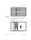
Table 3-1 lists various peripherals and their corresponding NI 8171 series
external connectors, bus interfaces, and functions.
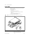
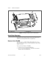
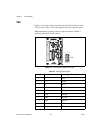
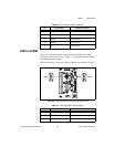
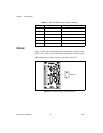
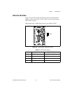
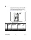
Note
In thischapter,the NI 8176 isshown in all illustrations.The connectors are insimilar
locations on all NI 8171 series modules.
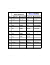
Table 3-1. NI 8171 Series Peripherals Overview
Peripheral
External
Connector
Function
NI 8171
Series Models
Video 15-pin DSUB
(standard VGA)
Integrated with Dynamic Video
Memory
All
Serial COM1 RS-232
Serial Port
(9-pin DSUB)
16550 serial port All
Serial COM2 RS-232
Serial Port
(9-pin DSUB)
16550 serial port NI 8176 and
NI 8175
10/100 Ethernet Ethernet Ethernet network connection All
Parallel Parallel Port
(IEEE 1284)
Extended capabilities All
USB 4-pin Series A
receptacle
Universal Serial Bus
(two ports on all models)
All
Keyboard/mouse PS/2 PS/2-style keyboard and mouse
(mouse requires PS/2 Y splitter)
All
PXI trigger Trigger Routing PXItriggers toorfrom the
backplane trigger bus
All
GPIB device GPIB (IEEE 488.2) General-Purpose Interface Bus NI 8176