


Chapter 3 I/O Information
NI 8171 Series User Manual 3-8 ni.com
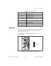
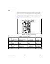
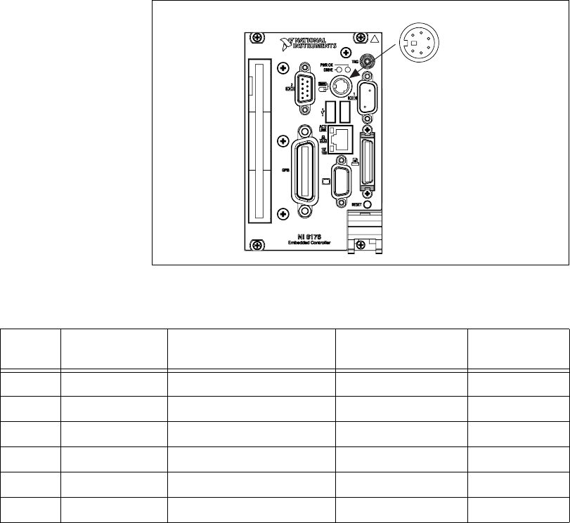
PS/2
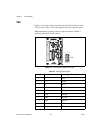
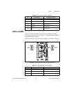
Figure 3-6 shows the location and pinouts for the PS/2 connector on the
NI 8171 series. Table 3-7 lists and describes the PS/2 connector signals.
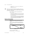
To connect both a PS/2 keyboard and PS/2 mouse to the NI 8171 series, use
the Y-splitter adapter cable (see Figure 4-1 in Chapter 4, Common
Configuration Questions) included with your controller.
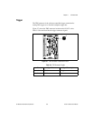
Figure 3-6. PS/2 Connector Location and Pinout
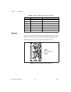
Table 3-7. PS/2 Connector Signals
Pin Signal Name Signal Description
Y-Splitt er
Keyboard
Y-Spl itter
Mouse
1 DATA Data Keyboard Data Keyboard Data Mouse
2 NC Data Mouse NC NC
3 GND Ground GND GND
4 +5V +5 V +5 +5
5 CLK Clock Keyboard Clock Keyboard Clock Mouse
6 NC Clock Mouse NC NC
PS/2
1
2
4
3
5
6