


Chapter 3 I/O Information
© National Instruments Corporation 3-3 NI 8171 Series User Manual
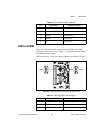
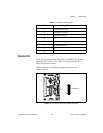
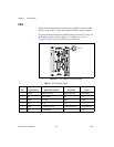
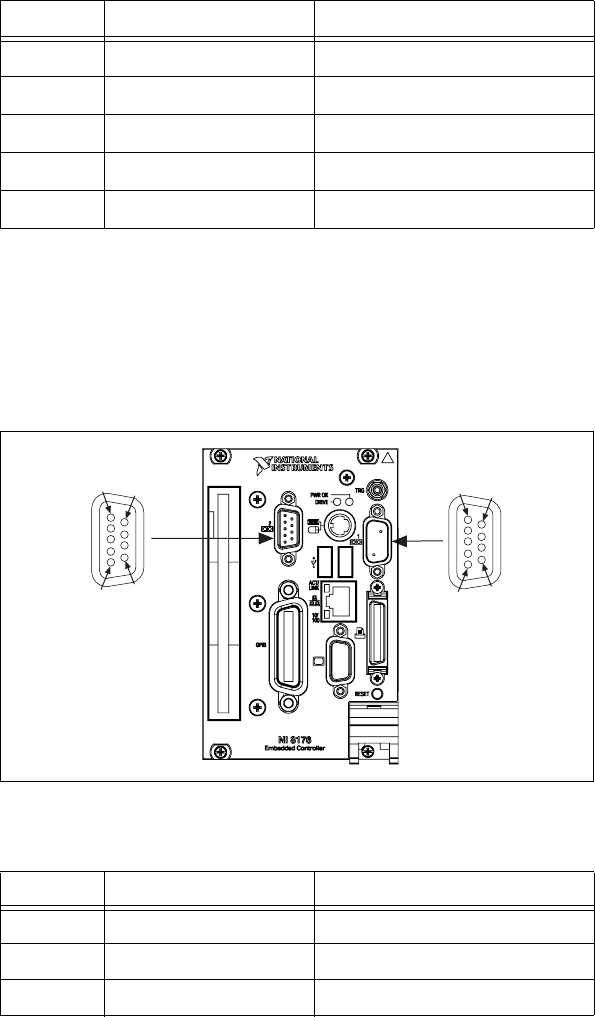
COM1 and COM2
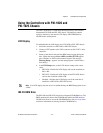
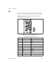
Figure 3-2 shows the location and pinouts for the COM1 and COM2
connectors on the NI 8171 series. Table 3-3 lists and describes the COM1
and COM2 connector signal.
AMP manufactures a serial port mating connector, part number 745491-5.
Figure 3-2.
COM1 and COM2 Connector Location and Pinout
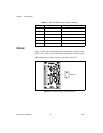
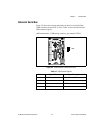
11 NC Not Connected
12 SD Serial Data
13 HSync Horizontal Sync
14 VSync Ve r tic a l S y n c
15 SC Serial Clock
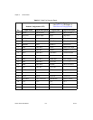
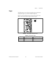
Table 3-3. COM1 and COM2 Connector Signals
Pin Signal Name Signal Description
1 DCD* Data Carrier Detect
2 RXD* Receive Data
3 TXD* Transmit Data
Table 3-2. VGA Connector Signals (Continued)
Pin Signal Name Signal Description
1
5
9
6
COM1
1
5
9
6
COM2