


© National Instruments Corporation 2-1 SC-2043-SG User Manual
Chapter 2
Installation and Configuration
This chapter describes the installation and configuration of your SC-2043-SG. The topics
discussed are connection of the SC-2043-SG to the DAQ board and switch and jumper
configuration for your SC-2043-SG.
Installation
Note: You must power off your computer—and the SC-2043-SG if externally powered—
before installing or making any connection to the SC-2043-SG.
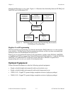
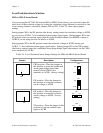
The SC-2043-SG includes two 50-pin cable connectors for signal connection to a DAQ board.
Connect the SC-2043-SG to your DAQ board I/O connector using the appropriate cable and
SC-2043-SG 50-pin connector. Table 2-1 lists the required cables and connectors to use with
each DAQ board option.
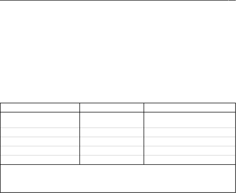
Table 2-1. Installation and Cabling Options for the SC-2043-SG
DAQ Board Required Cabling SC-2043-SG 50-Pin Connector
68-pin MIO E Series
boards
1
R6850 or SH6850 MIO (J10)
50-pin MIO boards
2
NB1 MIO (J10)
100-pin MIO boards
3
R1005050 MIO (J10)
Lab-PC+, DAQPad-1200 NB1 Lab/1200 (J9)
DAQCard-1200 PR50-50F Lab/1200 (J9)
1
To install the SC-2043-SG with any of these boards, refer to the installation guide of the cable kit for instructions.
2
The NB-MIO-16H and AT-MIO-16H boards have a maximum gain of 8 and are not intended for interfacing to low-level
signals. Therefore, you should not use these boards with the SC-2043-SG.
3
The SC-2043-SG connects only to pins 1–50 (ACH<0..15>) of the 100-pin MIO boards.
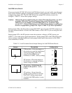
You can mount the SC-2043-SG in a rack-mount chassis using the mounting holes in the four
corners of the SC-2043-SG board.
The SC-2043-SG is installed. You are now ready to install and configure your software. If you
are using NI-DAQ, LabVIEW, or LabWindows/CVI, refer to the installation instructions to
install and configure your software.
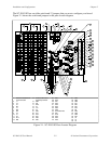
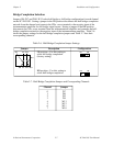
Board Configuration
Note: You must configure your DAQ board analog channels for NRSE (nonreferenced
single-ended) inputs for use with the SC-2043-SG.