


Contents
© National Instruments Corporation vii SC-2043-SG User Manual
Figures
Figure 1-1. The Relationship between the Programming Environment,
NI-DAQ, and Your Hardware ............................................................................. 1-3
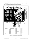
Figure 2-1. SC-2043-SG Parts Locator Diagram ................................................................... 2-2
Figure 3-1. Full-Bridge Connection to the SC-2043-SG........................................................ 3-8
Figure 3-2. Half-Bridge Connection to the SC-2043-SG....................................................... 3-8
Figure 3-3. Quarter-Bridge Connection to the SC-2043-SG.................................................. 3-9
Figure 4-1. SC-2043-SG Block Diagram ............................................................................... 4-2
Tables
Table 2-1. Installation and Cabling Options for the SC-2043-SG........................................ 2-1
Table 2-2. Power Supply Selection....................................................................................... 2-3
Table 2-3. Onboard/External Excitation Jumpers................................................................. 2-4
Table 2-4. Local Excitation Sense Jumper Settings for MIO and MIO E Series Boards ..... 2-5
Table 2-5. Local Excitation Sense Jumper Settings for Lab/1200 Series Boards................. 2-6
Table 2-6. Half-Bridge Completion Jumper Settings ........................................................... 2-7
Table 2-7. Half-Bridge Completion Jumpers and Corresponding Channels ........................ 2-7
Table 2-8. Quarter-Bridge Completion Resistors and Corresponding Channels.................. 2-8
Table 3-1. Pin Assignments for the MIO I/O Connectors .................................................... 3-2
Table 3-2. Pin Assignments for the Lab/1200 I/O Connector .............................................. 3-4
Table 3-3. MIO (J10) I/O Connectors Signal Summary....................................................... 3-5
Table 3-4. Lab/1200 (J9) Signal Summary........................................................................... 3-6
Table 3-5. Screw Terminals J1–J6 Signal Summary ............................................................ 3-7
Table 3-6. Offset Nulling Adjust Potentiometer and Corresponding Channel ..................... 3-9
Table 3-7. Nulling Resistor and Corresponding Channel ..................................................... 3-10