


Chapter 3 Signal Connections
© National Instruments Corporation 3-3 SC-2043-SG User Manual
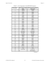
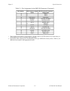
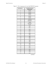
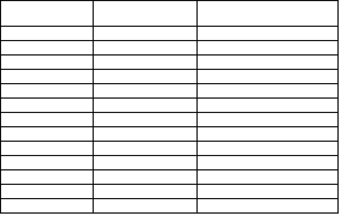
Table 3-1. Pin Assignments for the MIO I/O Connectors (Continued)
Pin Numbers MIO Connector Signal
Names
MIO E Series I/O Connector
Signal Names
38 †† TRIG1
39 †† TRIG2
40 EXTCONV* CONVERT*
41 SOURCE1 GPCTR1_SOURCE
42 GATE1 GPCTR1_GATE
43 OUT1 GPCTR1_OUT
44 †† UPDATE*
45 GATE2 WFTRIG
46 OUT2 STARTSCAN
47 SOURCE5 GPCTR0_SOURCE
48 GATE5 GPCTR0_GATE
49 OUT5 GPCTR0_OUT
50 FOUT FREQ_OUT
† These signals are not routed to screw terminals. All other signals on the I/O connectors are routed directly to
screw terminals (J1–J6) for convenient signal termination.
†† The function of this connector pin varies depending on the type of MIO Series board you have. Refer to your
MIO board user manual for the appropriate pin name.