


Theory of Operation Chapter 4
SC-2043-SG User Manual 4-4 © National Instruments Corporation
Filtering
Each channel of the SC-2043-SG has a postgain, lowpass filter. This filter is a single-pole,
buffered, RC filter with a cutoff frequency of 1.6 kHz.
I/O Connectors and Breakout Screw Terminals
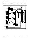
The outputs of all eight channels are connected to the ACH<0..7> analog input channel pins on
the MIO I/O connector and the Lab/1200 I/O connector. All the remaining pins, except two, on
these connectors are mapped to breakout screw terminals (J1–J6). These two pins are +5 V
(pin 34 on the MIO and pin 49 on the Lab/1200 I/O connectors) and DGND (pin 33 on the MIO
and pin 50 on the Lab/1200 I/O connectors). Refer to Chapter 3, Signal Connections, for the pin
assignments of the I/O connectors and their mapping to the screw terminals.
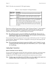
Excitation Voltage Source
The SC-2043-SG has an onboard excitation voltage source for Wheatstone bridge excitation.
This source is powered by the +5 V power supply and is routed to eight output screw terminal
pairs (±EX<0..7>), one pair per channel. The excitation source provides an adjustable, regulated
voltage output with a range of 1.5 to 2.5 VDC, controlled by a potentiometer (R2), and short-
circuit current limiting (approximately 1 A). The factory-default onboard excitation source
setting is 2.5 V. Screw terminals on J7 can connect an external excitation source of up to
10 VDC to the SC-2043-SG. Two jumpers select whether the onboard excitation source or the
external excitation source is routed to the output screw terminal pairs ±EX<0..7>. The offset
nulling circuitry also uses the excitation source output as a reference.
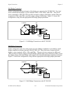
You can locally sense the exact level of the excitation voltage by routing the excitation voltage
via jumpers W2 and W8 to ACH0 or ACH8 of the MIO board or to ACH0 on a Lab/1200 board.
Refer to Chapter 2, Installation and Configuration, for further information on excitation source
configuration.
Note: There is
NO onboard overvoltage protection and current limiting protection for the
external excitation inputs. Therefore, if you select external excitation, you
MUST
ensure that your excitation supply does not exceed 10 V and is current-limited.
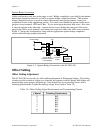
Power Supply
The SC-2043-SG contains an onboard power switch (SW1) to either power the SC-2043-SG
from the DAQ board or draw power from an external +5 V supply. Fuses F1 and F2 limit the
external +5 V power supply input to 1A at +5 V. The SC-2043-SG also has a spare fuse, F3, as
shown in Figure 2-1. From the +5 V power supply, an onboard DC-DC converter generates a
±15 V source, which is used to power the analog circuitry. The +5 V power supply also powers
the onboard excitation supply. A green LED indicates that the board is receiving power.