


Chapter 3 Signal Connections
© National Instruments Corporation 3-7 SC-2043-SG User Manual
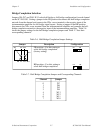
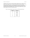
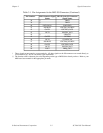
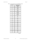
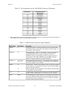
Table 3-5 lists the screw terminals (J1–J6) signal summary.
Table 3-5. Screw Terminals J1–J6 Signal Summary
Signal Name Description
CH<0..7>± Input Channels—These inputs are the input signals for analog channels
0 through 7.
±EX<0..7> Voltage Excitation Outputs—These output signals route the excitation
voltage supply (internal or external) to the sensors connected to these
channels.
Others All other screw terminals provide signal termination for the remaining I/O
lines of the DAQ board, except ACH<0..7>, +5 V, and one DGND line.
Refer to Tables 3-1 and 3-2 for these signal pin numbers.
If you are not using the sticker labels that come in the SC-2043-SG kit, the
numbers silkscreened on the board beside these screw terminals are the
pin numbers of the MIO and Lab/1200 I/O connector pins to which they
are mapped.
There are two additional screw terminal blocks, J7 and J8, shown in Figure 2-1. Screw terminal
block J7 is for external voltage excitation input signals, which hook up to the +EX and -EX
terminals. When the SC-2043-SG is configured for external excitation, the ±EX inputs are
routed directly to the ±EX<0..7> excitation output screw terminals.
Note: The -EX input signal is connected to DGND on the SC-2043-SG. Because this low-
impedance connection can cause a ground loop, which may affect your measurements,
your excitation voltage source
MUST be floating.
Screw terminal block J8 is for external +5 V power inputs, which hook up to the +5 V signal and
ground terminals. When the SC-2043-SG is configured for external power these inputs provide
power to the SC-2043-SG.
Note: The ground input signal is directly connected to DGND on the SC-2043-SG. In order
to avoid a ground loop, which may affect your measurements, your +5 V power supply
MUST be floating.
Analog Input Connections
Sensor Connection to the SC-2043-SG
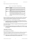
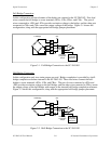
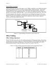
You can connect strain gauges to the SC-2043-SG in full-bridge, half-bridge, and quarter-bridge
configurations. See Chapter 2, Installation and Configuration, to make sure that you have
configured the SC-2043-SG channels correctly before you connect any sensors to them.
Note: Configure any unused channels for full-bridge connections and short their input screw
terminals (CHn
±
) to their excitation return screw terminals (-EXn).