


Signal Connections Chapter 3
SC-2043-SG User Manual 3-6 © National Instruments Corporation
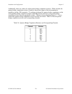
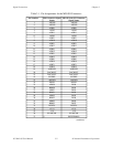
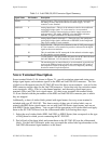
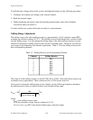
Table 3-4. Lab/1200 (J9) I/O Connector Signal Summary
Signal Name Pin Number Description
AGND 11 Analog Ground—This pin provides the AC noise current return point for
the analog circuitry and for the onboard excitation supply. It is also
routed to a screw terminal.
AISENSE 9 Analog Input Sense—This pin is the reference node for the conditioned
strain gauge bridge signals. It is also routed to a screw terminal.
AISENSE is directly connected to the excitation supply return and is
earth-grounded. This makes AISENSE a low impedance reference;
therefore, all signals referenced to it MUST be floating.
ACH<0..7> 1–8 Analog Input Channels 0 through 7—These pins carry the conditioned
strain gauge bridge signals (referenced to AISENSE) to the DAQ board.
They are not routed to screw terminals.
DGND 13
50
Digital Ground—This pin is the reference for the +5 VDC power supply.
It is also routed to a screw terminal to provide a reference for the digital
signals at the screw terminals.
This pin establishes the DC return path for the onboard excitation supply.
It is not routed to a screw terminal.
+5 V 49 +5 VDC Source—This pin provides DC power for the SC-2043-SG from
the Lab/1200 board. It is not routed to a screw terminal.
Others Others The remaining pins are routed directly to screw terminals to provide easy
access to the additional analog, digital, and counter/timer I/O signals of
the DAQ board. Refer to the Signal Connections chapter in your DAQ
board user manual for pin descriptions.
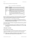
Screw Terminal Description
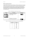
Screw terminal blocks J1–J6, shown in Figure 2-1, provide excitation output and strain gauge
bridge signal inputs, and terminate signals on the MIO and Lab/1200 I/O connectors. Two sets
of labels are silkscreened onto the SC-2043-SG board for these screw terminals—one set for the
MIO connector and the other for the Lab/1200 connector. Notice that only the excitation output
screw terminals, +EXn, -EXn (n is the channel number), and the analog signal input screw
terminals CHn+ and CHn- have signal names. All other screw terminals on terminal blocks
J1–J6 are labeled with the pin numbers of the MIO and Lab/1200 I/O connector pins to which
they are mapped.
Additionally, a sheet of sticker labels printed with signal names for every screw terminal is
included with your SC-2043-SG. This sheet consists of three sets of sticker labels, one set
printed with MIO Series signal names, one set with Lab/1200 Series signal names, and one set
with MIO E Series signal names. You can peel off the appropriate set of sticker labels and apply
them on the SC-2043-SG board over the silkscreened labels by following these steps:
1. Select the set of sticker labels (MIO, Lab/1200, or MIO E Series) that corresponds to the type
of DAQ board to which you are connecting the SC-2043-SG.
2. Peel off each of the three labels and mount them on the SC-2043-SG over the silkscreened
labels. For the Lab/1200 boards, make sure you match the sticker label signal numbers to the
Lab/1200 silkscreened signal numbers on the board.