


CRU Replacement and Server Upgrades 4-19
Replacing or Adding DIMMs
The following subsections provide the procedures for configuring and upgrading
system memory. Use these procedures when replacing or adding dual inline
memory modules (DIMMs) to your system. When adding or changing memory
in a CPU module the same changes must be must be made to the other CPU
module to provide total system redundancy and mirroring.
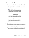
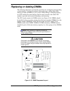
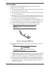
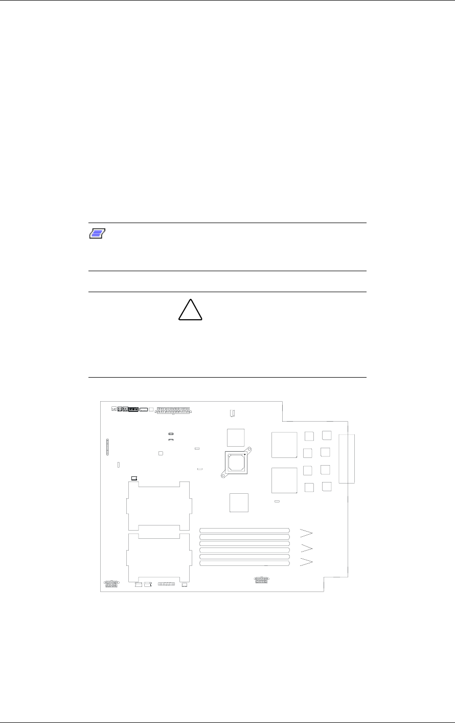
The CPU board contains six DIMM sockets (see Figure 4-18). DIMMs should
be installed in the six sockets starting from the lowest number (DIMM #1) to the
highest number (DIMM #6). Each 168-pin socket can hold a single 72-bit
DIMM module with 128MB, 256MB or 512MB of memory. DIMMS must be
installed in pairs of the same memory capacity (i.e., three groups of two DIMMs
each.)
Note: When replacing or upgrading DIMMs the
replacement DIMMs must be of the same specifications of
all the installed DIMMs.
!
CAUTION
Electrostatic discharge (ESD) can damage components;
place them on an antistatic surface. Add or replace DIMMs
on the CPU board using an antistatic wrist strap attached to
chassis ground.
CPU #2
CPU #1
A
B
C
D
E
F
Group 1
Group 2
Group 3
A
DIMM #1
B
DIMM #2
C
DIMM #3
D
DIMM #4
E
DIMM #5
F
DIMM #6
Figure 4-18. DIMM Component Layout