


1-22 System Overview
System Components and Module Set
The following sections describe the system components and module sets inside the
server.
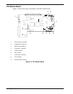
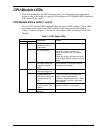
CPU Modules
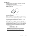
The server has two CPU modules that provide Dual Modular Redundancy (DMR). The
CPU modules are numbered 1 and 2, left to right as seen from the front of the tower
system. The CPU modules are numbered 1 and 2, top to bottom as seen from the front
of the rack-mount system. See Figure 1-4. Each CPU module has two status indicators
that are listed along with a description of each in Table 1-3. Table 1-7 summarizes the
features of a CPU module.
Table 1-7. Features of the CPU Module
Feature Description
Upgradable
multiple processor
slots
Two processor sockets are available on the CPU board for one or two
processors.
Upgradable
memory
Six DIMM sockets on the CPU board. Can contain a minimum of 256 MB up
to a maximum of 3 GB of Synchronous Dynamic Random-Access (SDRAM)
two-way interleaved system memory.
SMP Supports two-way Symmetric Multiprocessing (SMP) when two processors
are installed.
Fans Three integrated fans that provide cooling for the CPU module.
The system runs identical applications in both CPU modules in lockstep. Thus, if one
CPU module fails, the second CPU module takes over the processing without any
interruption to the current application running on the system. Note that this type of
failure is transparent to the user.
In simplex mode the system is operating with only one CPU module and one PCI
module. Thus, the failure of one CPU module or one PCI module causes the whole
system to fail. A fault-tolerant system should not run in the simplex mode for any
longer than necessary for upgrading or repair.
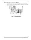
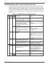
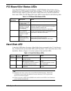
PCI modules
The server has two PCI modules that are CRUs, hot pluggable, and fault-tolerant. Each
PCI module contains a PCI board that transfers data from PCI devices to the CPU. The
PCI module is fault-tolerant such that if one stops functioning the other PCI module
takes over.
The PCI modules are numbered 1 and 2, left to right as seen from the front of the tower
system. The PCI modules are numbered 1 and 2, top to bottom as seen from the front of
the rack-mount system. See Figure 1-4. Each PCI module includes four status indicators
that are listed along with a description of each in Tables 1-1 and 1-2. Table 1-8
summarizes the features of a PCI module.