


System Overview 1-11
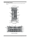
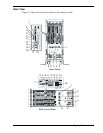
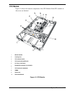
CPU Module
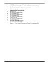
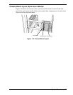
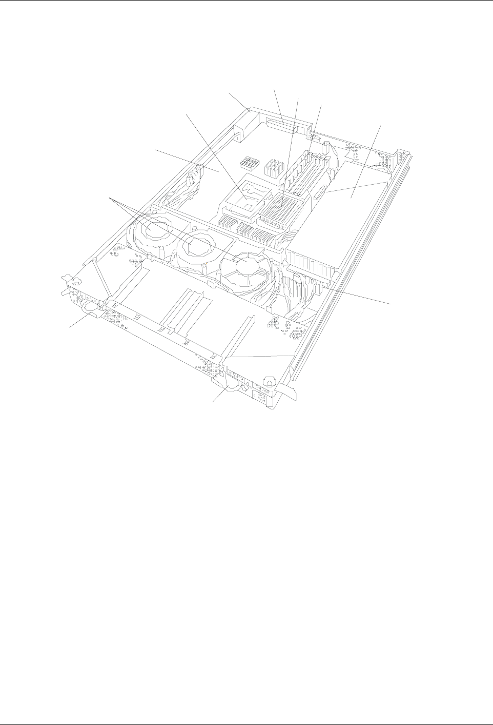
Figure 1-6 shows the internal components of the CPU Module. Both CPU modules in
the server are identical.
1
2
3
4
5
6
7
8
9
10
1
1
Module handle
2
Cooling fans
3
CPU module board
4
CPU socket #2 (additional)
5
AC inlet (in the back)
6
Backboard connector (in the back)
7
CPU socket #1 (standard)
8
DIMMs
9
Power unit
10
Power backboard
Figure 1-6. CPU Module