


2. Installation and Connections
28
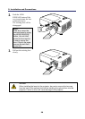
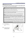
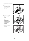
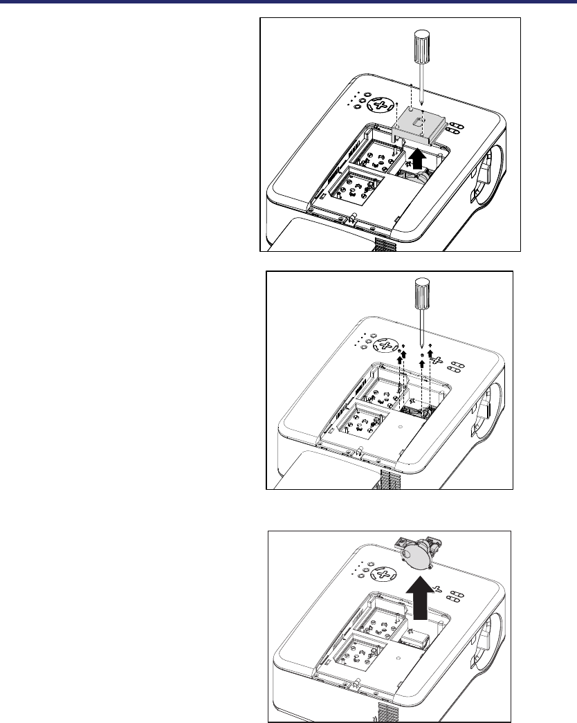
3.
Remove the screws
from the color wheel
cover. Lift cover in the
direction shown and
place on a clean, dust
free surface.
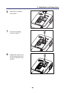
4.
Unscrew the retaining
screws on the
four-segment color
wheel.
Note:
Improper (loose)
installation of the color
wheel prevents an
image from being
displayed.
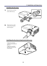
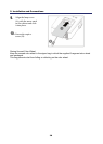
5.
Lift the unit in the direc-
tion shown.