


E–11
M
E
N
U
E
N
T
E
R
C
A
N
C
E
L
SELECT
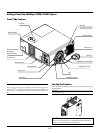
POWER
STATUS
ON
/
STAND BY
SOURCE
AUTO ADJUST
RGB
INPUT
OUTPUT
AUDIO
IN
INOUT
OUT
PC-CONTROL S-VIDEO VIDEO
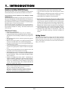
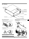
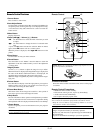
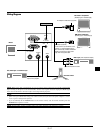
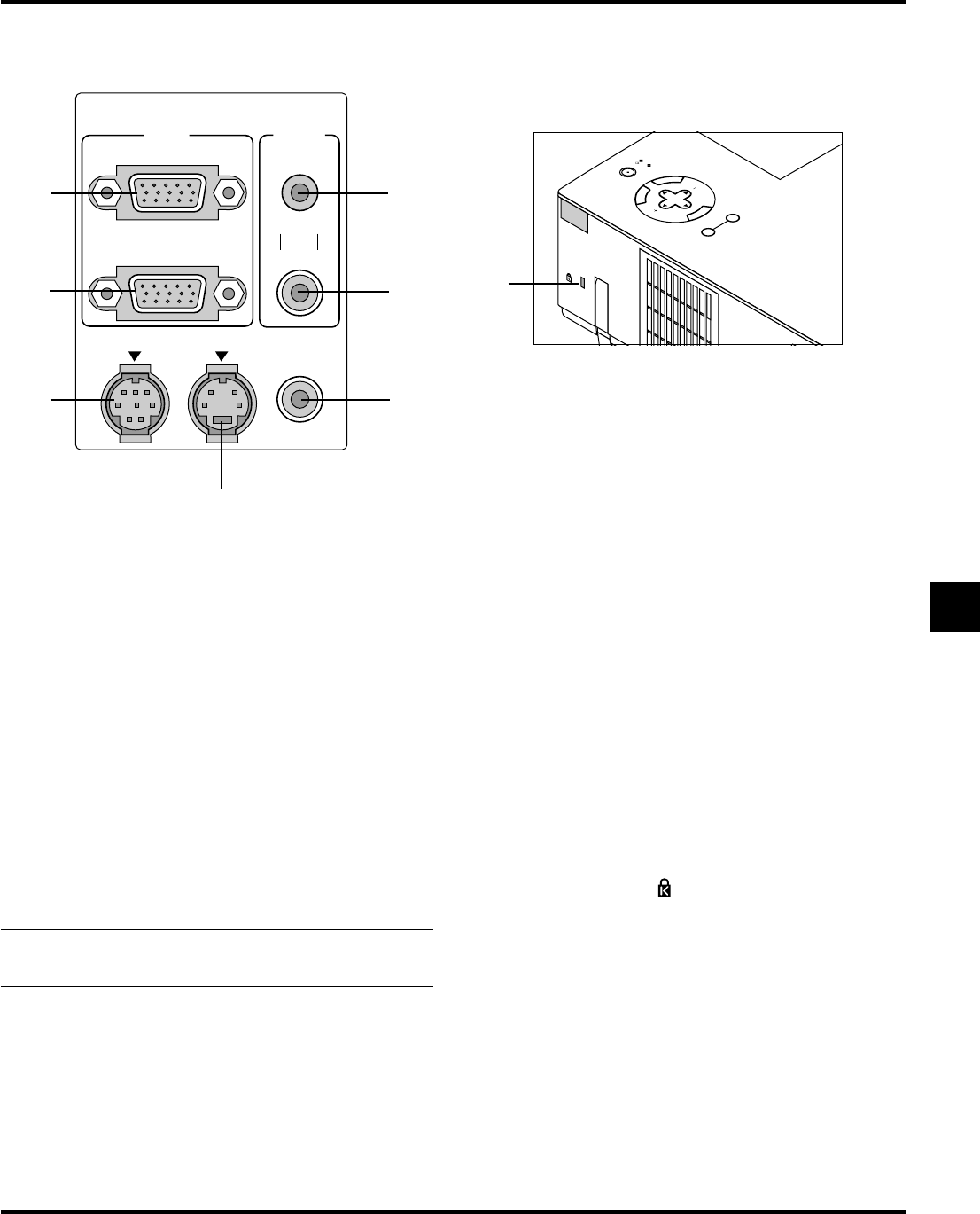
Terminal Panel Features
1
1. RGB Input Connector(Mini D-Sub 15 pin)
Connect your PC or other RGB equipment. Use the supplied sig-
nal cable to connect to a PC.
2. RGB Monitor Output Connector (Mini D-Sub 15 pin)
You can use this connector to loop your computer image to an
external monitor from the RGB input source.
3. Audio Input / Output Mini Jack
This is where you connect audio output from your computer. Or
connect additional external speakers here to listen to audio coming
from your Video or S- Video input.
4. Audio Input / Output Connector (RCA)
This is where you connect audio output from a VCR, DVD player,
or laser disc player. Or connect additional external speakers to lis-
ten to audio coming from your RGB source.
NOTE: Either connector 3 or 4 can be used for input or output, how-
ever they cannot both be used for input simultaneously. It can dam-
age your equipment.
5. Video Input (RCA)
Connect a VCR, DVD player, laser disc player, or document cam-
era here to project video.
6. S-Video Input Port (Mini DIN 4 Pin)
Connect the S-Video input from an external source like a VCR.
7. PC Control Port (Mini DIN 8 Pin)
Use this port to connect your PC to control your projector. This
enables you to use your PC and serial communication protocol to
control the projector. If you are writing your own program, typical
PC control codes are on page E-40.
A cap is put on the port at the factory. Remove the cap when using
the port.
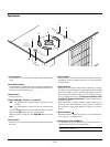
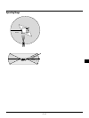
8. Built-in Security Slot (
)
This security slot supports the MicroSaver ® Security System.
MicroSaver ® is a registered trademark of Kensington Microware
Inc. The logo is trademarked and owned by Kensington Microware
Inc.
7
Slot for Kensington
MicroSaver Security System
8
2
3
5
6
4