


11
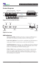
4xN 10/100/1000 Span iMatrix Switch
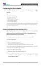
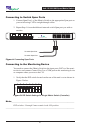
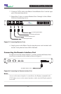
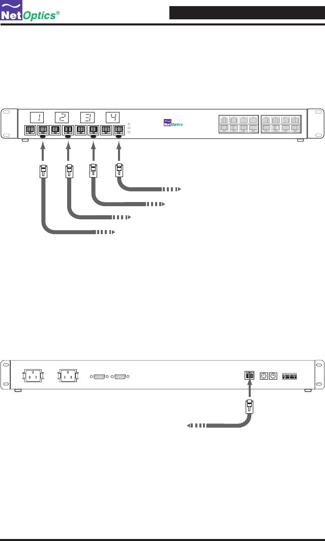
2. Connect a CAT5e cable to the iMatrix Switch Monitor Port 1 and the input
port of the monitoring device.
3. Repeat Step 3 above to connect Monitor Ports 2 through 4 of the iMatrix
Switch to a monitoring device.
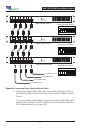
Figure 7: Connecting Monitor Ports
4. Supply power to the iMatrix Switch using the power cords included with
the unit. Verify that the Power LEDs illuminate.
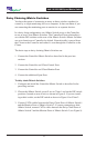
Connecting the Remote Interface Port
In order to access the remote interfaces, you must connect the Remote Inter-
face Port to a network switch or hub as shown in Figure 8.
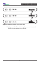
Figure 8: Connecting the Remote Interface Port
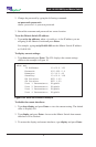
Note: ________________________________________________________________
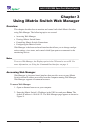
Access to the remote interface is controller by the Display command in the
CLI. To have access to the remote interfaces, make sure the Display option is
set to ON.
______________________________________________________________________
To network switch or hub
CONTROL PORT 2CONTROL PORT 1
OFF
13456782
11 12
13 15 1614
9
10
34
5786
1
2
4x16 10/100/1000 Span Port Switch
1
Daisy ChainDaisy Chain
2
Monitor 2Monitor 1
Daisy ChainDaisy Chain
Monitor 4Monitor 3
To monitoring device NIC 3
To monitoring device NIC 4
To monitoring device NIC 1
To monitoring device NIC 2