


13
4xN 10/100/1000 Span iMatrix Switch
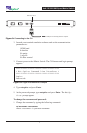
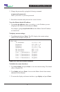
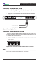
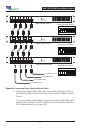
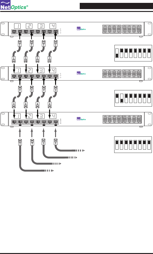
Figure 9: Connecting Daisy Chained Monitor Ports
4. Connect the supplied Mini-DIN cable between Daisy Chain Port OUT of
the Controller iMatrix Switch and Daisy Chain Port IN of iMatrix Switch
Client 1.
If you are installing a third iMatrix, connect the supplied Mini-DIN cable
between Daisy Chain Port OUT of iMatrix Switch 2 and Daisy Chain Port
IN of iMatrix Switch 3 (see Figure 10).
11 12
13 15 1614
9
10
34
5786
1
2
4x16 10/100/1000 Span Port Switch
1
Daisy ChainDaisy Chain
2
Monitor 2Monitor 1
Daisy ChainDaisy Chain
Monitor 4Monitor 3
iMatrix Switch Client 2
iMatrix Switch Client 1
Controller iMatrix Switch
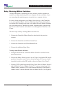
OFF
13456782
Master DIP Switch Settings
OFF
13456782
Client 1 DIP Switch Settings
OFF
13456782
Client 2 DIP Switch Settings
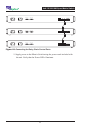
11 12
13 15 1614
9
10
34
5786
1
2
4x16 10/100/1000 Span Port Switch
1
Daisy ChainDaisy Chain
2
Monitor 2Monitor 1
Daisy ChainDaisy Chain
Monitor 4Monitor 3
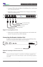
To monitoring device
To monitoring device
To monitoring device
To monitoring device
11 12
13 15 1614
9
10
34
5786
1
2
4x16 10/100/1000 Span Port Switch
1
Daisy ChainDaisy Chain
2
Monitor 2Monitor 1
Daisy ChainDaisy Chain
Monitor 4Monitor 3