


12
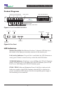
4xN 10/100/1000 Span iMatrix Switch
Daisy Chaining iMatrix Switches
You have the option of connecting as many as three switches together for
control by a single monitoring device or computer. It does not matter if you
are connecting the monitoring ports to one device or separate devices.
In a daisy chain confi guration, one iMatrix Switch serves as the Controller
to one or two Client iMatrix Switches. The Controller/Client relationship is
set with the DIP switches on the rear of the iMatrix Switch. iMatrix Switches
are set to function as a Controller by default. Network traffi c is passed from
the Clients to the Controller and control is sent through the Controller to the
Clients.
The basic steps to daisy chaining iMatrix Switches are:
1. Connect the Controller iMatrix Switch as described in the previous
sections.
2. Connect the Controller and Client Control Ports
3. Connect the Controller and Client Monitor Ports
4. Connect the additional Span Ports
To daisy chain iMatrix Switches:
1. Confi gure and install the Controller iMatrix Switch as described in the
preceding sections.
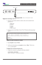
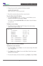
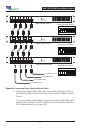
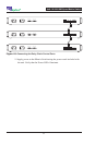
2. Choose the iMatrix Switch you will use as Client 1 and set the DIP switch
positions (located on rear of unit) as shown in Figure 9. If you are install-
ing a third switch, set the DIP switch as shown in Figure 9 for Client 2.
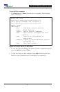
3. Connect CAT5e cables between the Daisy Chain Ports of iMatrix Switch 1
and the Monitor Ports of iMatrix Switch 2. If you are connecting a third
iMatrix Switch, connect CAT5e cables between the Daisy Chain Ports of
iMatrix Switch 2 and the Monitor Ports of iMatrix Switch 3 (see Figure 9).