


ASI-IP-GTW User's Manual
Page 20
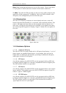
1.1.1.17 Connecting the Video Gateway to the AC Power Supply
To connect the unit to the local AC power supply:
1. Ensure that the local ac power supply is switch OFF.
2. Connect the ac power lead to the Video Gateway mains input
connector and then the local mains supply.
2.3.3 Optional DC Power Supply
The ASI-IP-GTW can be delivered with a 48 VDC power supply for use
in environments where this is required. The DC power can tolerate a
voltage range of 36 – 72 VDC. Please refer to
Appendix B: Technical Specification for a detailed specification of the
power supply.
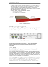
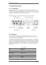
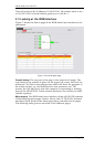
Units delivered with DC power supply, has a 3–pin male power D-SUB
connector in stead of the standard Mains Power Connector. Also a
female 3-pin D-SUB connector is supplied.
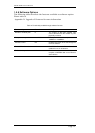
The pin assignment is shown in
Table 4.
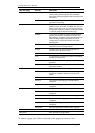
Table 4 DC power connector pin assignment
To connect the unit to the local DC power supply:
1. Use a soldering tool to attach the supplied loose female power D-
SUB connector to your power leads (not supplied).
2. Connect the power leads to your local power supply.
3. Connect the DC power connector, with attached power leads, to the
Video Gateway power input connector.
Warning: If the terminal screw has to be replaced, use an M4x12mm
long pozidrive panhead. Using a longer screw may cause a safety
hazard.
Warning: Do not overload wall outlets and extension cords as this can
result in a risk of fire or electrical shock. As no power switch is fitted in
this unit, ensure that the local ac power supply is switch off before
connecting the supply cord. The unit is not fitted with an on/off switch.
Ensure that the socket-outlet is installed near the equipment so that is
easily accessible. Failure to isolate the equipment properly may cause a
safety hazard.
Pin (placement) Specification
1 (top)
+ (positive terminal)
2 (middle)
- (negative terminal)
3 (bottom) Chassis Ground