


ASI-IP-GTW User's Manual
Page 21
2.4 Signal Connections
2.4.1 Introduction
All signal connectors are located at the rear of the ASI-IP-GTW. For
detailed specifications of the different interfaces, please refer to Chapter
0. Please ensure that specified cables are used in order to ensure signal
integrity and compliance with EMC requirements.
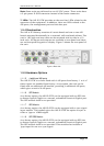
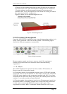
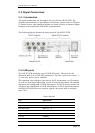
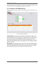
The following figure shows the back panel of the ASI-IP-GTW.
Figure 6. Rear panel connectors
2.4.2 ASI ports
The ASI-IP-GTW provides up to 8 DVB ASI ports. The unit can be
delivered with 4 or 8 DVB ASI connectors. For the 4 ASI port version, 1,
2, 3 or all 4 ports can be enabled.
The operator can configure the unit as an IP transmitter, an IP receiver,
or to IP bi-directional operation. In the IP transmitter mode, all enabled
ASI ports are configured as DVB ASI inputs. In the IP receive mode, the
ASI ports are configured as DVB ASI outputs. In IP bi-directional mode,
half the DVB ASI ports are used as inputs, the other half as outputs
(see
2.2.6)
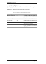
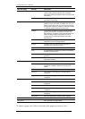
Table 5. ASI ports
Item Specification
Safety status SELV
Type Analogue
Connector name ASI 1,2,3,..., 8
Connector type BNC 75 ohm socket
Signal Compliant with EN50083-9: 1998 Table B.1
Line rate 270Mbit/s
Data rate 0,1-213Mbit/s