


ASI-IP-GTW User's Manual
Page 60
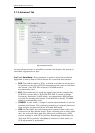
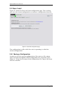
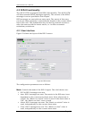
Current freq. offset: This shows the offset between the internal clock
(in idle state) and the external clock reference.
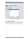
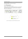
4.1.4 LED descriptions
(Separate 1PPS/10MHz module only)
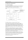
Each input connector has two LEDs associated with it; one yellow and
one green LED. The yellow LED is lit when the input is enabled. The
green LED is lit when the unit has locked correctly to the signal, as
shown in the following figure.
Figure 32. LED description for separate 1PPS/10MHz interface module