


NTI SERIMUX SERIES CONSOLE SWITCH
28
12VDC
2A
-
+
NTI
NETWORK
TECHNOLOGIES
INCORPORATED
Tel :330-5 62-70701275 Danner Dr
Aurora, OH 44202 www.nti1.com
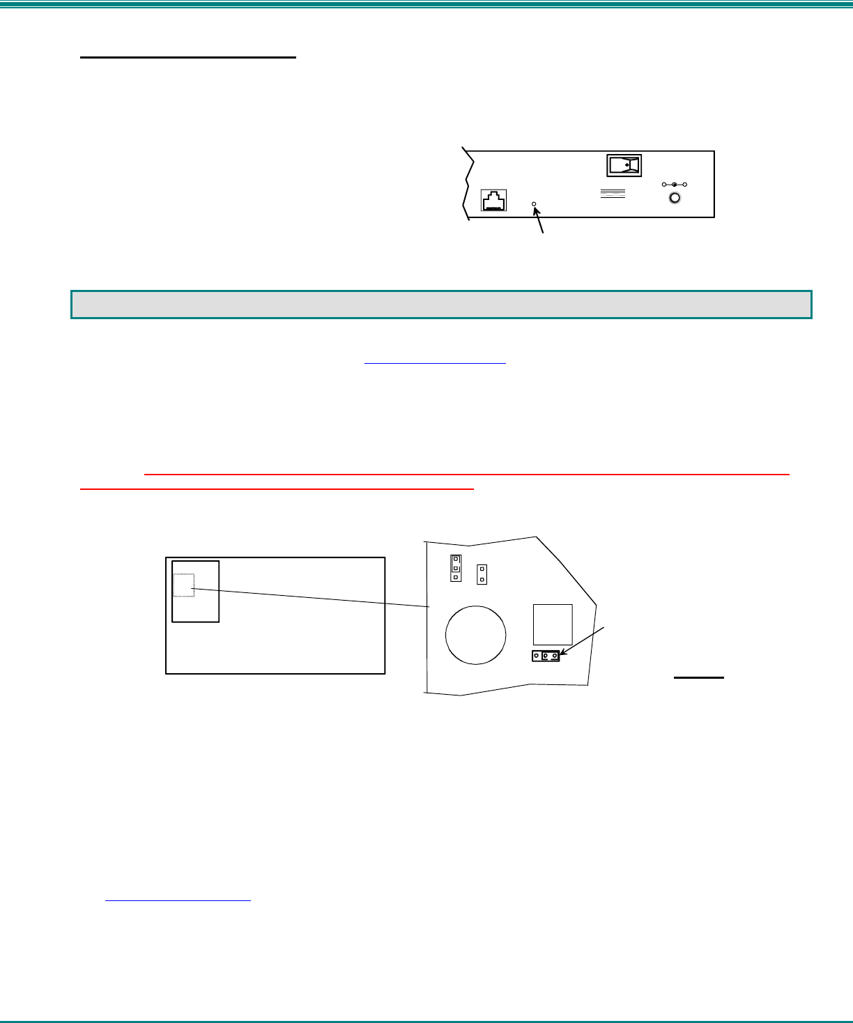
RESET
CONSOLE
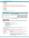
Rear View of SERIMUX
Press button to re-initialize
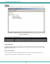
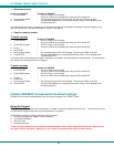
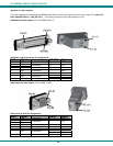
Using The "RESET" Button
If the keypad method of re-initializing the SERIMUX fails to work, the "RESET" button on the back of the SERIMUX may be used.
The SERIMUX should be OFF before pressing the "RESET" button.
1. Press and hold the "RESET" button using a small object that will fit through the hole in the back of the SERIMUX. (See Fig.
22).
2. Turn ON the SERIMUX.
3. Wait 3 seconds.
4. Release the button.
Caution: During initialization, the customer modified
parameter values will be replaced with the factory default
values (for default values, see page 31, Appendix A),
user names and passwords will be erased.
Figure 22- Location of RESET button
FIRMWARE UPGRADE
It may be desired to upgrade the firmware that controls the Console Switch as soon as improved versions become available.
Once the firmware file has been downloaded from www.networktechinc.com
to a local CPU, follow these instructions to install it.
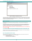
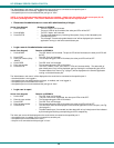
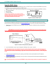
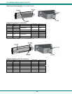
1. Remove the top of the SERIMUX and move the jumper at JP3 to the 1-2 position, to disable the memory write protection.
(See Fig. 23)
Warning!
Be sure to turn OFF the power and unplug the SERIMUX power cord from the AC adapter before
removing the top cover. Do not change any other jumper position.
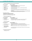
Figure 23- Location of write-protection jumper JP3
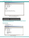
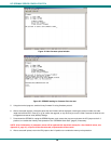
2. Log-in as administrator, at port 0 (port 0 configured for 9600 bps, 8-bit, no parity, 1 stop bit).
Note: The upgrade process can be started from any port, but the loading file transfer has to be performed from port 0.
During the transfer and the internal upgrade, all ports, except port 0, and all users are disconnected. The SERIMUX unit
will then be reset (initialized to default settings), regardless of whether the administrator chooses to confirm the upgrade
or not.
3. Locate on the local hard disk the binary file containing a valid firmware version (downloaded from the NTI website at
www.networktechinc.com)
.
4. From the "Firmware" menu (pg 19) press [2], then [Y] to confirm. All other ports will be disconnected and disabled during the
firmware update procedure.
Note: Proceeding past this point will reset the SERIMUX to factory default settings, whether the upgrade is completed or
not.
Front of Serimux
Rear of Serimux
Battery
JP3
123
Jumper at JP3
shown in position
for memory write
protection
enabled
Overhead View of Serimux