


NTI SERIMUX SERIES CONSOLE SWITCH
4
12VDC
2A
-
+
NTI
NETWORK
TECHNOLOGIES
INCORPORATED
Tel :330-5 62-70701275 Danner Dr
Aurora, OH 44202 www.nti1.com
RESET
CONSOLE
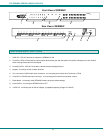
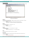
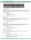
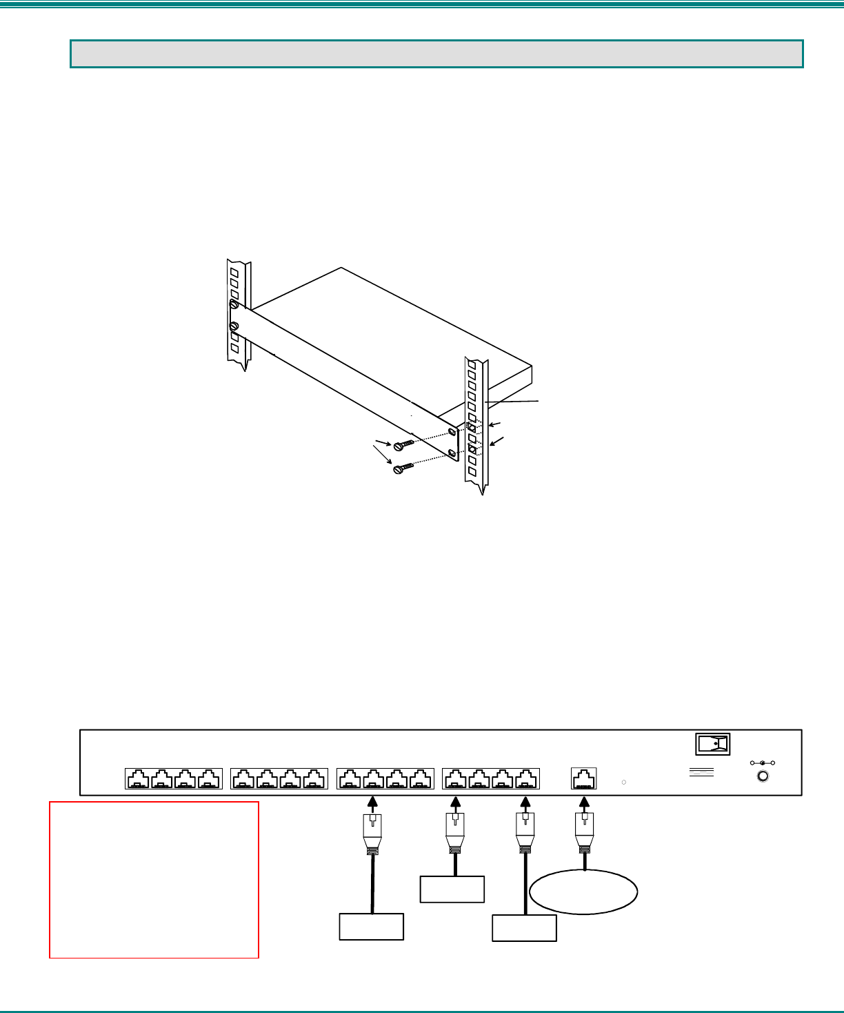
Rear View of SERIMUX
9101112
13
141516
12345678
USER DEVICE
(VT100, ANSI serial console,
PC w/ Terminal Emulation
Program)
SERVER
IC CHIP
PROGRAMMER
CNC
PUNCHPRESS
RJ45 Male Connector
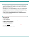
INSTALLATION
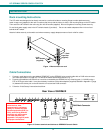
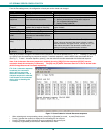
Rack mounting Instructions
The NTI switch was designed to be directly mounted to a rack and includes a mounting flange to make attachment easy.
Install 4 cage nuts (supplied) to the rack in locations that line up with the holes (or slots) in the mounting flange on the NTI switch.
Then secure the NTI switch to the rack using four #10-32 screws (supplied). Be sure to tighten all mounting screws securely.
Do not block power supply vents in the NTI switch chassis (if provided) . Be sure to enable adequate airflow in front of and
behind the NTI switch.
Attach all cables securely to the switch and where necessary supply adequate means of strain relief for cables.
Figure 1- Mount switch to a rack
Cable Connections
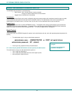
1. Connect a serial device to the port labeled "CONSOLE" on the SERIMUX using a serial cable with an RJ45 male connector
(see cable specification on page 30). This will be the default administrator device. (Fig. 1)
2. Connect each additional serial device or host to be connected by the SERIMUX to any remaining port (1-16/24/32) using a
DTE or DCE type serial cable. It may be necessary to add one of the cable adapters (supplied) detailed in Appendix C (page
31) between the device port on the serial device or host and the RJ45 connector.
3. Follow the "Initial Startup" instructions that follow.
Figure 2- Connect terminals and devices to SERIMUX Console Switch
Cage Nuts
Rack Screws
Rack
(supplied)
10-32
(supplied)
Note: There are two types of
serial devices, data
communication equipment
(DCE)(i.e. modem) and data
terminal equipment (DTE) (i.e.
CPU), each having different
connector pin assignments.
The cable adapters (see
Appendix C on page 32) make
the proper connections.