


NTI KEEMUX Series PS/2 KVM Switch
7
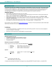
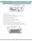
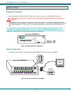
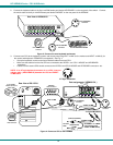
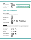
2. Connect Local CPUs to any remaining consecutive ports on the master as described under INSTALLATION on page 3.
3. Connect the RMT extension cables:
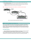
a. With an RMT extension cable (REXT-SR-xx), connect the master’s “DAISY OUT” port to slave #1’s “DAISY IN” port.
b. With another RMT extension cable, connect slave #1’s “DAISY OUT” port to slave #2’s “DAISY IN” port. (See Fig. 8
below.)
c. Apply additional RMT extension cables until all slave units are connected together.
NOTE: If switches are not being cascaded, then the “DAISY IN” and “DAISY OUT” ports will not be used.
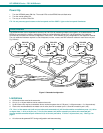
Figure 7- Connect remote extension cables between cascaded units
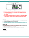
USING THE NTI KEEMUX PS/2 KVM SWITCH
Control over the CPUs attached to the NTI KEEMUX is achieved through operation of the KEEMUX. Once the KEEMUX is
properly connected, the KEEMUX will enable a connection to be made between the CPUs attached to its CPU x, and VIDEO x
ports and the keyboard, monitor, and mouse attached to the PS/2 DEVICES and MONITOR ports. The LEDs on the control
panel of the KEEMUX will illuminate depending on which port (and associated CPU) is being connected to the keyboard, monitor,
and mouse. The choice of which CPU will be connected to the keyboard, monitor, and mouse is determined by controlling the
KEEMUX either through the front control panel on the KEEMUX, by keyboard control, or by optional methods such as RS232 or
an On Screen Display (OSD).
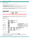
Front Panel Control
There is a touch-switch and LED on the front panel of the KEEMUX for each connected CPU. Pressing any touch-switch on
the front panel of the KEEMUX will connect the selected CPU to the keyboard, monitor, and mouse.
Holding down any front panel touch-switch for more than 2 seconds will cause the KEEMUX to cycle through all modes of
operation: COMMAND, SCAN, BROADCAST, and NORMAL (described on pages 9 and 10). Three LEDs on the front panel
indicate when these modes are enabled. Release the touch-switch when the desired mode is enabled. When no mode LEDs are
illuminated the user is in Normal Mode controlling directly the CPU to which the user is connected through the KEEMUX.
5VDC
2A
- +
V
I
D
E
O
8
V
I
D
E
O
7
V
I
D
E
O
6
V
I
D
E
O
5
V
I
D
E
O
4
V
I
D
E
O
3
V
I
D
E
O
2
V
I
D
E
O
1
M
O
N
I
T
O
R
Mouse
CPU 1
C
P
U
1
C
P
U
2
C
P
U
3
C
P
U
4
CPU 2CP U 3CP U 4
Ke yb oar d
CP U 5
C
P
U
5
C
P
U
6
C
P
U
7
C
P
U
8
CPU 6CPU 7CP U 8
Da i s y Dai s y
O ut I n
NTI
Tel:330-562-7070
Fax:330-562-1999
1275 Danner Dr
Aurora, OH 44202
www.nti1.com
R
PS/2 D EVICES
5VDC
2A
-
+
V
I
D
E
O
8
V
I
D
E
O
7
V
I
D
E
O
6
V
I
D
E
O
5
V
I
D
E
O
4
V
I
D
E
O
3
V
I
D
E
O
2
V
I
D
E
O
1
M
O
N
I
T
O
R
Mouse
CPU 1
C
P
U
1
C
P
U
2
C
P
U
3
C
P
U
4
CPU 2CPU 3CPU 4
Keyboard
CPU 5
C
P
U
5
C
P
U
6
C
P
U
7
C
P
U
8
CPU 6CPU 7CPU 8
Daisy Daisy
Out In
NTI
Tel:330-562-7070
Fax:330-562-1999
1275 Danner Dr
Aurora, OH 44202
www.nti1.com
R
PS/2 DEVICES
5VDC
2A
-
+
V
I
D
E
O
8
V
I
D
E
O
7
V
I
D
E
O
6
V
I
D
E
O
5
V
I
D
E
O
4
V
I
D
E
O
3
V
I
D
E
O
2
V
I
D
E
O
1
M
O
N
I
T
O
R
Mouse
CPU 1
C
P
U
1
C
P
U
2
C
P
U
3
C
P
U
4
CPU 2CPU 3CPU 4
Keyboard
CPU 5
C
P
U
5
C
P
U
6
C
P
U
7
C
P
U
8
CPU 6CPU 7CPU 8
Daisy Dai sy
Out I n
NTI
Tel:330-562-7070
Fax:3 30- 562- 1999
1275 Danner Dr
Aurora, OH 44202
www.nti1.com
R
PS/2 DEVICES
TO SLAVE 1
"DAISY IN"
REXT-SR-xx
DAISY OUT
SLAVE #1
MASTER
SLAVE #2
REXT-SR-xx
TO SLAVE 2
"DAISY IN"