


NTI KEEMUX Series PS/2 KVM Switch
17
RS232 CONTROL
(Optional)
RS232 Connections and Configuration
Remote Connection
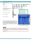
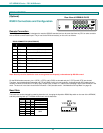
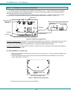
The RS232 Interface (optional) is designed to meet the RS232C standard and can be controlled from any CPU or other controller
with an RS232 communications port. The pin-out for the DB-9 connector(s) on the unit is as follows:
RS232 CONNECTOR (DB-9 FEMALE)
PIN SIGNAL FUNCTION
1 CD Carrier Detect
2 TXD Transmit data (RXD at host)
3 RXD Receive data (TXD at host)
4 DTR Data terminal ready
5 GND Signal ground
6 DSR Data set ready
7 RTS Request to send
8 CTS Clear to send
9 - No connection
Note: Security must be disabled or user access granted on the port(s) to be selected by RS-232 control.
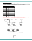
On the DB-9 female connector, pins 1 (DCD), 4 (DTR), and 6 (DSR) are shorted and pins 7 (RTS) and 8 (CTS) are shorted.
Therefore, host handshaking is bypassed and TXD and RXD are the only active signals. A straight through DB-9 cable (not null
modem) will work for most CPUs. To daisy chain multiple units, a Matrix Y-1 cable is used (see page 18) for each KEEMUX in the
chain. The last unit in the chain should have DIP switch 1 ON (see table under "Unit Address and Loop Back" on page 18).
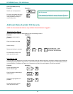
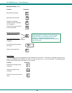
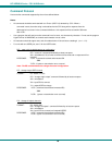
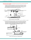
Baud Rate
The baud rate can be changed by powering down the unit, changing the 8 position RS232 dip switch on the rear of the KEEMUX,
and then powering back up. This table shows how to set the baud rate.
DIP SWITCH BAUD RATE
4 3 2
OFF OFF OFF 300
OFF OFF ON 600
OFF ON OFF 1200
OFF ON ON 2400
ON OFF ON
ON ON OFF
ON ON ON
9600
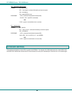
ON
OFF
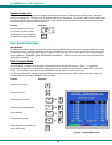
1 2 3 4 5 6 7 8
Rear View of KEEMUX-P4-RS
5VDC
2A
-
+
V
I
D
E
O
4
V
I
D
E
O
3
V
I
D
E
O
2
V
I
D
E
O
1
M
O
N
I
T
O
R
Mouse
CPU 1
C
P
U
1
C
P
U
2
C
P
U
3
C
P
U
4
CPU 2CPU 3CPU 4
Keyboard
D aisy Daisy
Out In
NTI
Tel:330-562-7070
Fax:330-562-1999
1275 Danner Dr
Aurora, OH 44202
www.nti1.com
R
PS/2 DEVICES
RS232
ON
OFF
1 2 3 4 5 6 7 8