


NTI KEEMUX Series PS/2 KVM Switch
21
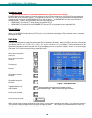
HOW TO DISABLE OPERATING MODES
The operating modes of the KEEMUX can be disabled if a user desires to do so. The Command Mode can be disabled
which would also disable the Scan and Broadcast Modes, or, the Scan and/or Broadcast Modes can be individually disabled
leaving the other features in Command Mode enabled.
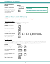
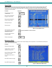
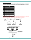
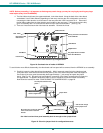
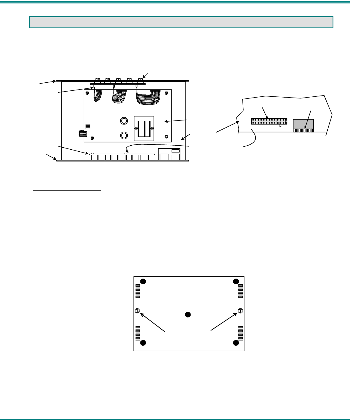
To disable these operating modes, the user must get access to the jumper block. This block is located close to the dip-
switches on the circuit board the keyboards plug into (called the digital board) inside the KEEMUX. (See Fig. 16.)
Figure 16- Location of the jumper block
If the unit is a rackmount style, the digital board is located directly beneath the cover of the unit, requiring the user to only remove
the 10 screws from the cover to get access. With the cover removed, the jumper block will be easy to locate. Follow the
instructions under "CONFIGURING THE JUMPER BLOCK" on page 22 to disable the desired mode(s).
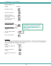
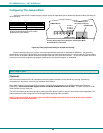
If the unit is in a plastic case, the digital board is located on the bottom of the case, requiring the user to partially disassemble the
unit to gain access to the jumper block.
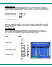
For models KEEMUX-Px in a plastic case:
1. Make sure the KEEMUX is completely disconnected from all CPU components. Be sure to unplug the KEEMUX from
the electrical outlet.
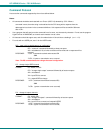
2. Remove the two philips-head screws from the underside of the KEEMUX and set the KEEMUX on a firm and flat
surface, bottom down. (See Fig. 17.)
Figure 17- Remove screws to open case
3. Remove the top half of the plastic case from the KEEMUX.
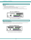
Philips-head screws
holding the plastic case
together
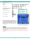
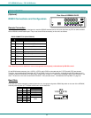
View of bottom of plastic case
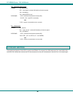
Video Board
Digital Board
The jumper block is located
below the LED board.
L
C
D
E
K
C
M
D
B
R
D
C
S
C
A
N
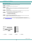
JUMPER BLOCK
DIP SWITCHES
Closeup view of jumper block on digital board.
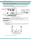
Disconnect video
ribbons here
15HD Connector
Overhead view of video board on top of digital board.
LED Board
Front Panel
Rear Panel