


NTI KEEMUX Series PS/2 KVM Switch
3
INSTALLATION
Prepare To Connect
1. Before connecting the KEEMUX to the CPUs, make sure all CPUs, the monitor, and the KEEMUX are turned OFF.
WARNING! DAMAGE MAY OCCUR TO THE CPU IF POWER IS NOT DISCONNECTED BEFORE CONNECTING OR DISCONNECTING
CABLES.
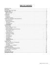
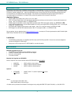
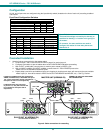
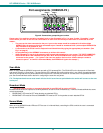
2. The dip-switches on the front panel are configurable for several tasks. Switches 1-6 are used for cascading actions (see
CASCADING on page 5) and switches 7 and 8 are for keyboard configuration. These keyboard configuration switches come
pre-configured with both in the “OFF” position. Do not change these settings, as this will cause the PS/2 keyboard to not
work.
FYI: Should switch 7 or 8 get changed to the “ON” position, it will be necessary to power-down the entire system
(including CPUs), change the dip-switches back to the “OFF” position, and then power the system back up. If it is
necessary to replace one PS/2 keyboard with another one, the keyboard can be hot-swapped without powering-down.
Refer to Fig. 1 for instructions on proper keyboard dip-switch configuration.
Figure 1- Keyboard dip-switch configuration
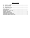
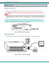
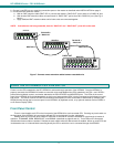
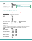
Make Connections
1. Connect the monitor cable to the 15HD female port labeled “MONITOR” on the rear panel of the KEEMUX.
Figure 2- Connect the monitor to the KEEMUX
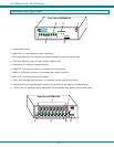
Front View of KEEMUX-P8
On
1
2345
678
Scan
Com
mand
Broad
cast
1 8
NTI
R
Network Technologies Inc
Switch 7 - OFF
Switch 8 - OFF
!
Rear View of KEEMUX-P8
5VDC
2A
-
+
V
I
D
E
O
8
V
I
D
E
O
7
V
I
D
E
O
6
V
I
D
E
O
5
V
I
D
E
O
4
V
I
D
E
O
3
V
I
D
E
O
2
V
I
D
E
O
1
M
O
N
I
T
O
R
Mouse
CPU 1
C
P
U
1
C
P
U
2
C
P
U
3
C
P
U
4
CPU 2CPU 3CPU 4
Keyboard
CPU 5
C
P
U
5
C
P
U
6
C
P
U
7
C
P
U
8
CPU 6CPU 7CPU 8
D aisy Daisy
Out In
NTI
Tel:330-562-7070
Fax:330-562-1999
1275 Danner Dr
Aurora, OH 4420 2
www.nti1.com
R
PS/2 DEVICES
VGA
Multi-Scan
Monitor
15HD Male
Video Connector
15HD Female
Video Connector
M
O
N
I
T
O
R