


NTI KEEMUX Series PS/2 KVM Switch
23
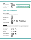
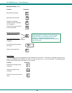
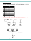
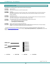
Configuring The Jumper Block
Once the jumper block is exposed, apply a jumper across the appropriate pins to disable the desired mode(s) according to
the chart below.
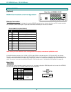
Pin Designation Mode
KCMD Command Mode*
BRDC Broadcast Mode
SCAN Scan Mode
*Note: Putting a jumper across pins KCMD to
disable Command Mode will also disable
Broadcast and Scan Modes.
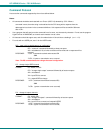
Figure 20- Place jumpers according to desired functionality
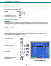
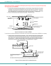
Once the desired jumpers are in place, reverse the disassembly process to re-assemble the KEEMUX. Be particularly
careful about connecting the ribbons back to the headers they were removed from and to fully insert the ribbons into the headers.
Note: The text on the video ribbons should face the right-hand side of the case after insertion. Do not turn the power ON until all
connections have been completely and properly made and the unit has been properly re-assembled.
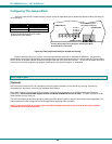
DDC SUPPORT
(Optional)
DDC information allows the CPU to automatically select the optimal resolution for the monitor by receiving, at power up,
information from the monitor concerning its resolution specifications.
When DDC Support is installed, the DDC information is acquired from the monitor by the KEEMUX when the KEEMUX is
powered-up. A monitor with DDC support must be connected to MONITOR for this to occur. The DDC information will be
made available at every CPU port.
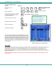
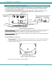
The DDC information can also be acquired by pressing the DDC button located on the front of the switch (when supported). This
button allows the monitor configuration to be changed without powering down the switch.
Note: In order for the CPU to correctly receive the DDC information from the switch at boot-up, the switch must be
powered up before all attached CPUs.
L
C
D
E
K
C
M
D
B
R
D
C
S
C
A
N
JUMPER BLOCK
DIP SWITCHES
Drawing shows jumper across SCAN pins, disabling Scan Mode.
Broadcast Mode is still enabled.
JUMPER (unused)
If the unit has an LCD
this jumper will be here.