


25
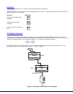
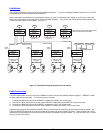
All the downstream switches should be powered ON before pressing any keyboard key. If there are USB extenders connected,
they should also be powered ON. An extra time of about 5 seconds after powering-ON the last unit may be needed to complete
the USB enumeration process. If the switch is a standalone unit (no downstream switches connected), the keyboard key could be
pressed immediately.
When a keyboard key is pressed, the master switch will start the process of detecting the configuration. This could take several
seconds, depending on how many switches are connected together. When configuration update is ready, the splash screen
disappears and the system is ready to operate. (If security mode is activated, the login window will be displayed on the screen).
The update-configuration function can be recalled at any time by entering into Command Mode and pressing the <Ctrlt> + <Tab>
keys
Note: The front panel buttons are used to operate only standalone switches. To operate a cascaded network of switches
use only OSD commands from Command Mode (see page 12).
After completing the configuration detection, the splash screen is turned OFF and the switches can be operated. All configuration
can be controlled from the keyboard, mouse and monitor through OSD menus (page 8).
DDC SUPPORT (OPTIONAL)
DDC information allows the CPU to automatically select the optimal resolution for the monitor by receiving, at power up,
information from the monitor concerning its resolution specifications.
When DDC Support is installed, the DDC information is acquired from the monitor by the UNIMUX switch when the UNIMUX is
powered-up
. A monitor with DDC support must be connected to MONITOR for this to occur. The DDC information will be
made available at every CPU port.
The DDC information can also be acquired by pressing the DDC button located on the front of the switch (see page
2, item 10). This button allows the monitor configuration to be changed without powering down the switch.
Note: In order for the CPU to correctly receive the DDC information from the switch at boot-up, the switch
must be powered up before all attached CPUs.
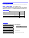
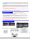
TECHNICAL SPECIFICATIONS
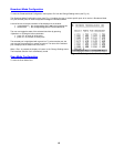
USB Type B USB Type A VGA Video
Pin # Signal Pin # Signal Pin # Signal Pin # Signal
1 +VCC 1 +VCC 1 RED 9 NC
2 - DATA 2 - DATA 2 GREEN 10 GND
3 +DATA 3 +DATA 3 BLUE 11 ID0
4 GND 4 GND 4 ID2 12 ID1
5TST 13HS
6 RED GND 14 VS
7 GREEN GND 15 ID3
8BLUE GND
21
43
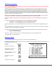
Mating face of a USB Type B Female
Mating face of a USB Type A Female
1
2
34
Barrel
(Inside
barrel)
(Outside
barrel)
Power Connector
2.1 mm x 5.5 mm Female
5VDC @ 2.0A OUTPUT
TECHNICAL SPECIFICATIONS
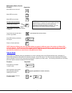
Mating face of a 15HD female
VGA VIDEO
4
2
3
51
10
98 6
7
15
14
13 12 11
DDC Support (Optional)
Option not available on 2 port switches.