


4
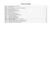
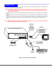
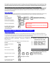
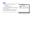
5. Using the USB cable ends of a USB-VEXT-xx-MM cable connect the USB type A device port of a USB CPU to the USB
type B port labeled "CPU 1" on the UNIMUX-USBV-4 USB KVM switch.
6. Using the 15HD male video connector ends of the same USB-VEXT-xx-MM, connect the video port of the same USB CPU
connected in step 5 to the female 15HD port labeled "VIDEO 1" on the UNIMUX-USBV-4 USB KVM switch . Be sure to
tighten the two screws on the cable connector to the UNIMUX-USBV-4 USB KVM switch securely. See Fig. 2.
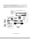
7. Repeat steps 5 and 6 for connecting each additional USB CPU to the ports labeled "CPU 2" and "VIDEO 2", "CPU 3" and
"VIDEO 3", etc.
Figure 2- Connect a CPU
U S B T y p e B
F e m a le C o n n e c t o r
U S B T y p e A F e m a l e
U S B T y p e A M a l e
U S B V E X T - x x - M M
1 5 H D F e m a l e
V i d e o C o n n e c t o r
U S B T y p e B
M a l e
1 5 H D F e m a l e
V i d e o C o n n e c t o r
R e a r V i e w o f W i n d o w s U S B C P U
V i d e o P o r t
I n p u t D e v i c e P o r t
C P U 4 C P U 3 C P U 2 C P U 1
5 V D C
2 A
-
+
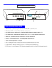
N E TW O R K TE C H N O L O G IE S IN C O R P O R A TE D 12 75 D an n er D rive , A uro ra O hio 44 202 3 30-562 -70 70 w w w .n ti1 .co m
N T I
R
U S B
D E V IC E S
M O N IT O R
V ID E O 1V ID E O 2V ID E O 3V ID E O 4
V I D E O 4
R e a r V i e w o f U N I M U X - U S B V - 4