


Document Ref: Nex8inst.doc/Rev0 09.07.00 Page 10 of 30 Originator MC Checked by AC__
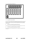
4.0 Panel Check
Ensure that the mains supply has been inspected and tested in accordance with BS5839 Part 1
and the current IEE regulations and that the system is correctly earthed.
4.1
Leave all test resistors in place and connect the 230V mains supply.
4.2 Switch on. The control panel should react as follows:
(i) The internal buzzer will sound
(ii) The “System on” LED will illuminate
(iii) The LCD will display a time [which needs to be checked)
5.0 Panel Configuration – Engineer’s Operating Instructions
NOTE: Please read the panel configuration options before proceeding to commissioning.
5.1 Introduction
The functions are intended to allow a complete system to be set up at site level. Three levels of
engineer functions are provided. The access system is arranged such that level 1 access only is
possible with code 1, levels 1 & 2 with code 2 and all levels with code 3. Level 1 functions are
intended for the end user. When the engineer functions are selected, the control panel in most
cases still fully operational i.e. an alarm condition will fully activate the panel. The only
options which cause the panel not to be fully operational are described later under “Status -
disabled” and “Sensor test”.
All engineering menu functions are available after operating the ACCESS CONTROLS key
switch and then pressing ENGINEER on the display, followed by input of the appropriate four-
digit access code.
If system is left in the engineers mode without controls being pressed, the panel will “time out”
to normal operation. Time-out periods vary, depending upon option selected, from 1 to 15
minutes.
5.2 Overview of Engineer’s Menu Options
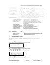
5.2.1 Access level 1 1278
1:SET TIME/DATE
2:ISOLATE DEVICES Single device, range, de-isolate all, read.
3:EDIT DEV/LOGO TEXT Via PC or special QWERTY keyboard.
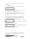
5.2.2 Access level 2 7218
4:CONFIGURE LOOP The panel will identify and report the type and quantity of sensors