


Document Ref: Nex8inst.doc/Rev0 09.07.00 Page 26 of 30 Originator MC Checked by AC___Approved by JBJ__
iii Compatible Loop Devices and Panel Responses
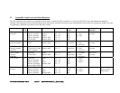
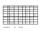
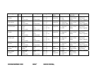
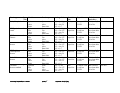
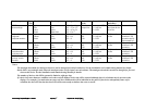
The following table shows all devices compatible with the panel. It shows the panel’s response to events from each device type, and indicates the change in
analogue value and input bits that will be displayed in the status mode. Note that some device types automatically receive cause effect outputs by default. Any such
programming is indicated in the default cause and effect column.
Device type Type
Code
Condition Panel response Analogue Value Status bits
(210)
Output bits Default cause
and effect
Comments
CEL sounder
controller
1 Quiescent
Input 1 operated
Input 2 operated
Input 3 operated
Circuit fault
None
Mode 1
Mode 2
Remote fault
Remote fault
AV = 16
AV = 64
AV = 48
AV = 4
AV = 4
000
000
000
000
000
0 = evacuate
1 = alert
2 = relay
Bit 0 set on
evacuate
CEL Loop
powered sounder
1 Quiescent
Fault
None
Remote fault
AV = 16
AV = 4
Echo
output bits
0 = evacuate
1 = alert
2 = not used
Bit 0 set on
evacuate
Series 90
sounder/ sounder
controller
1 Quiescent
Circuit fault or fault
input operated
None
Remote fault
AV = 16
AV = 4
Echo
output bits
0 = evacuate
1 = alert
2 = not used
Bit 0 set on
evacuate
XP95 sounder/
sounder
controller
1 Quiescent
Circuit fault
None
Remote fault
AV = 16
AV = 4
Echo
output bits
0 = evacuate
1 = alert
2 = not used
Bit 0 set on
evacuate
CEL I/O unit 2 Quiescent
Input 1 operated
Input 2 operated
Input 3 operated or
power supply failed
None
Fire
Input
Remote fault
AV = 16
AV = 64
AV = 48
AV = 4
000
000
000
000
0 = relay 1
1 = relay 2
2 = relay 3
Series 90 3-way
I/O unit
2 Quiescent
Input 1 operated
Input 2 operated
Input 3 operated
None
Fire
Input
Remote fault
AV = 16
AV = 16
AV = 16
AV = 16
000
1XX
01X
001
0 = relay 1
1 = relay 2
2 = relay 3
X means status
does not affect
panel status