


Document Ref: Nex8inst.doc/Rev0 09.07.00 Page 24 of 30 Originator MC Checked by AC__
Appendices
i Technical Specifications
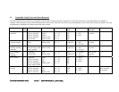
NOTE: Due to the wide scope of panel options, we strongly recommend the use of our
battery calculation chart which is available on PC disk or as hard copy. The information
below should not be used to calculate standby battery size.
Power Supplies
Mains input voltage: 230V AC -6% + 10%
System operating voltage: 24V DC
Quiescent current at 24V DC: 375mA (A1557. A1508, A1575 – no loop cards)
Quiescent loop card current 65mA + 1.3 x loop current
Loop card max. current 200mA
Power supply max: 5 Amps @ 24V DC
Alarm power output max: 1 Amp per circuit @ 24V DC (Note 3)
Auxiliary output max: 0.5 Amp @ 24V DC (Note 4)
Battery charger output: 1.5 Amps (Note 5)
Battery type: 24V sealed lead acid
Output Circuits
Alarm circuits: 2
Alarm circuit monitoring: Open/short circuit (Note 6)
Repeater output: Serial data RS485 (Note 7)
Printer output: Parallel
Multiplex inputs/outputs: 248 (via A1535/A1536 boards)
Panel Network: Connection of 15 panels via Network data link
Alarm fuse rating: 1 Amp thermal resetable fuse
Battery fuse rating: 6.3 Amp (20mm glass)
Auxiliary fuse rating: 0.5 Amp (20mm glass)
Mains fuse rating: 3 Amp (20mm glass)
Input Circuits
Detection loops: Cable 1.5mm (max. length - 2km)
Detection loop fuse rating: 250mA thermal resetable
No. of sensors on loop: 126 maximum (Note 9)
Relay Outputs
2 independent relays are provided which operate as follows:
Fire relay: 1 double pole changeover, operates on any fire alarm
Fault relay: 1 single pole changeover operates on any fault signal
All relay contacts are rated at 24V DC 1 Amp.
Cable Terminations
Mains terminals: Shrouded, marked & fused, accept max 2.5mm
2
cables
Alarm and loop terminals: Screw terminals, accept max. 2.5mm
2
cables
All other terminals: Screw terminals, accept max. 2.5mm
2
cables
All terminal functions are identified by screen printing on the circuit boards.