


Document Ref: Nex8inst.doc/Rev0 09.07.00 Page 25 of 30 Originator MC Checked by AC__
NOTES:
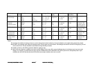
1. We strongly recommend the use of the Battery and Loop calculator for assessing the
correct size of the standby batteries and correct loop function in all conditions.
2. Quiescent current is stated assuming mains failure conditions, therefore the general
fault LED will be illuminated and the fault buzzer will sound.
3. The total current drawn by both alarm circuits operating must not exceed 2 Amps.
4. The total DC auxiliary current drawn must not the values stated in the Technical
Specification. The power supply current limiting will operate if ratings are exceeded.
5. The battery charger employed is the constant voltage type and the current will be
dependent upon the state of charge of the battery.
6. Alarm line monitoring operates using polarity reversal. All alarm sounders and/or
visual alarms must be made polarity sensitive for line monitoring to operate correctly.
7. Repeater data output is available at terminals in the control panel. Two cores are
required for the connection of repeater panels. The maximum cable length between the
control unit and any repeater unit is 2000 metres. The cable must be suitable for RS485
data such as Belden 8132 or equivalent. If power is provided from the control unit, 2
additional cores are required.
8. The control panel provides an RS485 multiplex data link for driving additional output
devices such as zonal relays, alarms, mimic indicators etc. The output functions are
programmable at site level.
9. The number of sensor devices may need to be reduced due to the power requirements
of the devices themselves. Fire sensors, heat smoke, call points etc. may be fitted in any
combination up to the maximum (126) addressing capability of the protocol. Zone
monitors in particular require a higher operating voltage and also draw significantly
more current from the control unit; reference to the system design manual is necessary
if zone monitors are to be used on the loop.
10. If any devices which contain an inductive coil (relays etc.) are connected to the panel,
these should be suppressed by connecting a diode across the positive and negative
connections of the coil.
ii Other Relevant Documentation
Sales Literature
Nexus 1-8 Loop Application Guide
Nexus 1-8 Loop User Instructions
Nexus Repeater Documentation
A1535 8 Way Relay Board Documentation
A1536 8 Way Alarm Board Documentation
PC-Based Software Programming Guide
Wiring Recommendations
Battery and loop Calculation Software