


10
I
NFRARED MAIN SYSTEM UNIT
STEP DESCRIPTION
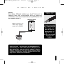
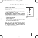
BE SURE TO OBSERVE PROPER
POLARITY WHEN EXTENDING
THE FLASHER WIRE.
The wire lead marked with a
gray stripe is positive (+); the
unmarked lead is negative (-).
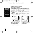
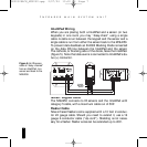
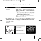
3. Test for shorts and
interference.
A) Reconnect the power supply. If the Power LED lights and the
IR Test LED stays off, unplug the connector from the power
socket and proceed to Step 4. The following LED conditions
show a fault:
•If Power LED is off there is a short between +12V and GND.
•If IR Test LED is on or flickers blue there is a short between
DATA and GND or interference is present.
Before you proceed to Step 4 consult the Troubleshooting
Section beginning on page 14.
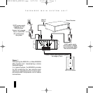
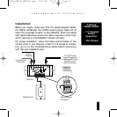
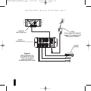
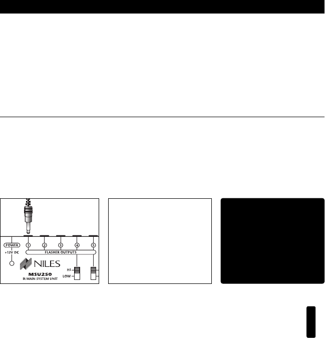
4. Plug the flashers into the
flasher outputs. If you need
to extend the wire, use
a 2-conductor 16 gauge
or larger (See “Tech Tip”
on page 6).
Route the connecting wire to the IR Main System Unit. Connect
the 3.5mm plug into the jack labeled “Flasher Output” on the
MSU250 (Figure 7).
“TECH TIP”
Make all final connections
to the MSU before
connecting the power
supply. This will avoid
potential damage
to components.
Figure 7
DS00328ACN_MSU250.qxp 2/27/04 10:10 AM Page 10