


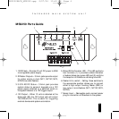
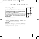
3-30V
AC/DC
STATUS
IN
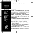
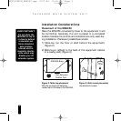
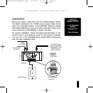
Installation
Before you begin, make sure that the sensor/keypad cables,
the flasher cables and the 12VDC power supply cable will all
reach the proposed location of the MSU250. Mark the cables
with labels describing where the cable originates (rather than
which terminal on the MSU250 it should connect).
For proper installation, follow the steps outlined below in the
correct order. If you discover a fault in the course of installa-
tion, go on to the Troubleshooting Guide before continuing
with the next installation step.
8
I
NFRARED MAIN SYSTEM UNIT
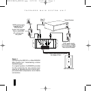
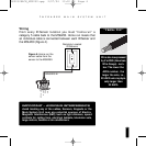
TOOLS
REQUIRED
• 1/8" Standard
Slotted
Screwdriver
• Wire Stripper
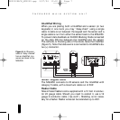
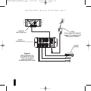
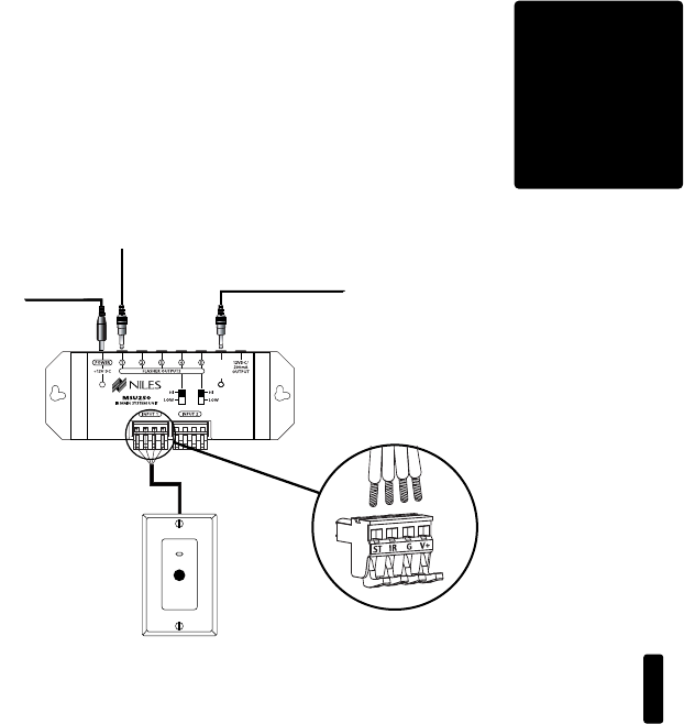
WS100 Sensor
To unswitched
AC Outlet
Figure 6:
MSU250
Installation.
MSU250 Sensor
Connection
MSU250
To Niles
IR Flasher
To 12V DC Power
Supply Plugged into
an switched AC Outlet.
Typically found in
back of a receiver.
DS00328ACN_MSU250.qxp 2/27/04 10:10 AM Page 8