


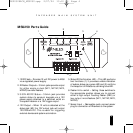
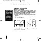
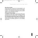
Installation Considerations
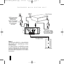
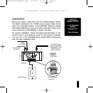
Placement of the MSU250
Place the MSU250 conveniently close to the equipment it will
be controlling. Generally, the unit is placed in a concealed
location because its controls and indicators are only used dur-
ing installation. Placement possibilities include:
1) Table-top (on the floor or shelf behind the equipment)
(Figure 2).
2) Wall-mount (affixed to the back of the equipment cabinet
or a nearby wall) (Figure 3).
5
I
NFRARED MAIN SYSTEM UNIT
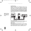
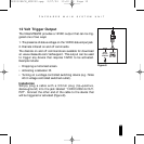
IMPORTANT
Do not place the
MSU250 on top of
or directly behind
a television set.
Some television
sets produce
intense electro-
magnetic interfer-
ence which may
disable your IR
extender system.
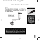
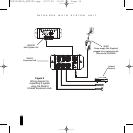
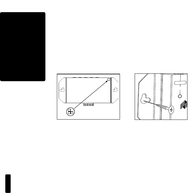
Figure 2: Table-top placement
Affix the enclosed self-adhesive
rubber feet to the base of the MSU250.
Self-Adhesive
Rubber Feet
1
2
3
POWER
+1
2V DC
FLASHER OUTPUTS
MSU
IR MAIN SYSTEM UNIT
INPUT 1
Figure 3: Wall-mount placement
Use sheetrock screws.
1234
POWER
+12V DC
3-30V
AC/DC
STATUS
IN
FLASHER OUTPUTS
MSU140
IR MAIN SYSTEM UNIT
INPUT 1
MSU250 Base
DS00328ACN_MSU250.qxp 2/27/04 10:10 AM Page 5