


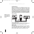
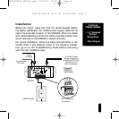
Wiring
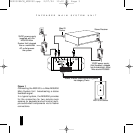
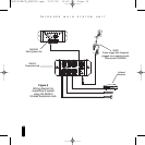
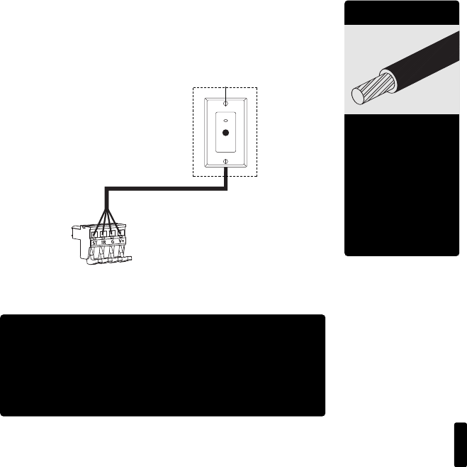
From every IR Sensor location you must “home-run” a
category 5 cable back to the MSU250. Home run means that
an individual cable is connected between each IR Sensor and
the MSU250 (Figure 4).
6
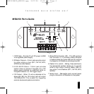
I
NFRARED MAIN SYSTEM UNIT
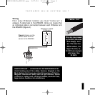
“TECH TIP”
Wire size is expressed
by it’s AWG (American
Wire Gauge) num-
ber. The lower the
AWG number, the
larger the wire, i.e.,
20 AWG wire is physi-
cally larger than
22 AWG.
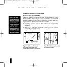
IMPORTANT – AVOIDING INTERFERENCE
Avoid locating any of the cables, Sensors, Keypads or the
Main System Unit near any potential sources of Electro-
Magnetic Interference (EMI), such as light dimmers, speed
controls for ceiling fans, electrical ballasts, television sets,
large motors, heaters or air conditioners.
Figure 4: Home run the
sensor cable from the
sensor to the MSU250.
D
A
T
A
S
T
A
T
U
S
G
N
D
+
12
V
Remotely Located
IR Sensors
SENSORS IN
DS00328ACN_MSU250.qxp 2/27/04 10:10 AM Page 6