


Nortel Networks 5399 Access Switch Hardware Installation Guide
Chapter 4 Troubleshooting Procedures
4-2
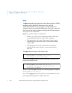
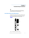
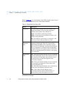
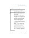
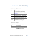
Refer to Table 4-1 for a description of the LEDs located on the front of
the Model 5399 Remote Access Concentrator Module.
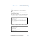
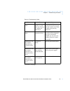
Table 4-1. Model 5399 Front Panel LEDs
(continued on next page)
LED(s) Description
Annunciator The Annunciator backlights the model number of the
module and indicates, by its color, the operational
condition of the module. The conditions are:
Green - The module is performing normally.
Amber - Some portion of the module has failed, or the
module is being initialized.
Off - The module is not receiving +5 volt power, or the
power level is below the reset limit (4.65 volts).
Segment
Connection
LEDs
These LEDs indicate which backplane Ethernet LAN
segments are being used. There are 12 green LEDs,
labeled S1 through S12, for the 12 Ethernet segments.
When an LED is illuminated, it indicates that the Remote
Access Concentrator is connected to the corresponding
backplane Ethernet LAN segment; when off it indicates
that the corresponding backplane Ethernet LAN segment
is not connected.
Module Status
LEDs
Init - Turns green when the Remote Access Concentrator
begins the initialization process after a power-up or reset.
This is the first LED that lights after power-up or reset.
The Init LED turns off after the diagnostics have
successfully completed.
Unit - Turns green after the Remote Access Concentrator
passes the power-up diagnostics. Turns amber if the
power-up diagnostics fail.
Net - Turns green after the Remote Access Concentrator
verifies that a valid Ethernet connection exists.
Attn - Turns amber when the Remote Access
Concentrator requires operator attention, that is, in
Monitor Mode or when the diagnostic tests fail.