


4-3
Chapter 4 Troubleshooting Procedures
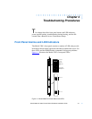
Nortel Networks 5399 Access Switch Hardware Installation Guide
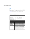
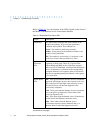
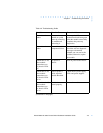
Table 4-1. Model 5399 Front Panel LEDs (continued)
(continued on next page)
LED(s) Description
Module Status
LEDs (continued)
Load - Turns green when the Remote Access
Concentrator is loading the operational image or
dumping a RAM image if there is a failure. The LED
turns amber if a load error is detected.
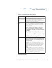
Network Status
LEDs
TEST - The network TEST indicator is ON (amber)
when the WAN Interface is looped back. Loopback
tests are activated either locally by the user or by the
telephone company.
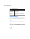
SYNC - The green SYNC indicator is ON (green)
when the WAN interface is synchronized with the
received network signal and is receiving proper framing
information.
LOS - The LOS indicator is ON (amber) when the
WAN interface is detecting invalid synchronization
pulses on the network interface receiver. When an LOS
condition exists, the WAN interface transmits a
YELLOW alarm to the remote system.
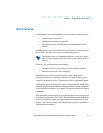
Alarm LEDs RED - The RED alarm indicator is ON (amber) during
a locally detected carrier failure.During the RED alarm
condition, a YELLOW alarm is transmitted across the
telephone network.
YELLOW - The YELLOW alarm indicator is ON
(amber) when receiving a YELLOW alarm condition
from the telephone network. This indicates a failure
detected at the other end of the link (the Central
Office).
BLUE - The BLUE alarm indicator is ON (amber)
when receiving an unframed, all-ones Alarm Indication
Signal (AIS) from the network. This condition exists
upon a loss of originating signal, or when any action is
taken that would cause a signal disruption.