


1
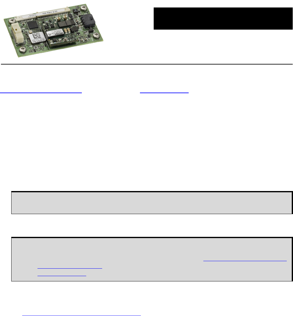
MEMS Interface Card
GM-14915118 Rev 4 December 2013
QUICK START GUIDE
This guide provides the basic information needed to set up and use your new NovAtel
®
MEMS Interface
Card (MIC). For more detailed information on the installation and operation of your MIC, download the
SPAN on OEM6 User Manual
from our web site at www.novatel.com.
BOX CONTENTS
In addition to this Quick Start Guide, the following is provided with your MIC:
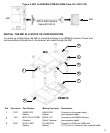
• 1 MIC to IMU interface cable
• 1 IMU mounting PCB (printed circuit board)
(a PCB is not included with the OEM-IMU-STIM300)
• Screws and standoffs for mounting the MIC
ADDITIONAL EQUIPMENT REQUIRED
The additional equipment listed below is required for a typical setup:
• An OEM615 receiver
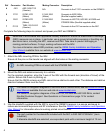
• An IMU (see the IMU Type column in Table 1, CONNECTIMU Commands on page 9)
• A 10-30 VDC power supply
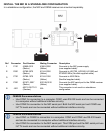
• A wiring harness to provide power to the P101 connector on the MIC (10-30 VDC).
• A wiring harness to connect the customers equipment to the P301 connector on the MIC.
• A quality, dual-frequency GNSS antenna such as the GPS-702-GG. See the NovAtel website
(www.novatel.com/products/gnss-antennas/
) for information on a variety of quality antennas
available to meet your form factor and performance needs.
• An antenna cable
• A Windows
®
based computer
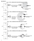
The MIC supports all OEM6
®
family receiver cards for communications. The OEM615 is the
only OEM6 family receiver card that can be directly integrated and powered by the MIC.
If the MIC is installed in a standalone configuration, a separate power supply is required for
the OEM6 family receiver. For information about the power supply requirements, refer to the
Technical Specification appendix for the receiver card in the OEM6 Family Installation and
Operation User Manual. This user manual is available from our website at
www.novatel.com
.