


4
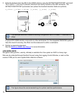
Complete the following steps to connect and power your MIC and OEM615.
1. Attach the IMU mounting PCB to the IMU.
Ensure all the pins on the header are aligned with the holes on the mating connector.
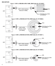
2. Mount the IMU and antenna securely to a vehicle.
For the simplest operation, align the Y-axis of the IMU with the forward axis (direction of travel) of the
vehicle. Ensure the Z-axis is pointing up.
Ensure that the GNSS antenna and IMU cannot move relative to each other. The distance and relative
direction between them must be fixed.
3. Use the standoffs supplied with the MIC to mount the OEM615 receiver in a secure enclosure to
reduce environmental exposure and RF interference. See the OEM6 Family Installation and Operation
User Manual for information about mounting printed circuit boards.
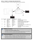
4
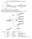
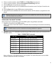
J301 ASP-163577-01
(Samtec)
N/A Connects to the P1101 connector on the OEM615
5
P701 53780-1070
(Molex)
51146-1000
(Molex)
Connects to ADIS IMUs
(NovAtel supplied cable)
6
P601 53780-2070
(Molex)
51146-2000
(Molex)
Connects to HG1700, HG1900, HG1930 and
STIM300 IMUs (NovAtel supplied cable)
7 P1101
TMM-110-03-G-D
(Samtec)
N/A Connects to the J301 connector on the MIC
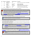
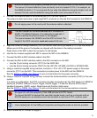
Assemble in accordance with applicable industry standards. Ensure all Electrostatic Discharge
(ESD) measures are in place, in particular, use a ground strap before exposing or handling any
electronic items, including the MIC, receiver and IMU. Take care to prevent damaging or
marring painted surfaces, O-rings, sealing surfaces and the IMU.
For more information about ESD practices, see the OEM6 Family Installation and Operation
User Manual available from our website at www.novatel.com.
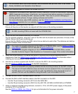
An IMU mounting PCB is not used with the STIM300 IMU.
For center of navigation diagrams of the ADIS and STIM300 IMUs, see the SPAN on OEM6
User Manual available from our web site at www.novatel.com.
For center of navigation diagrams of the HG1700, HG1900 and HG1930 IMUs, contact
NovAtel Customer Support. See Questions or Comments on page 12 for contact
information.
The part number for the standoffs included with the MIC is RAF-M21073005AL7 (Irwin
Industrial).
If alternate standoffs are selected, use equivalent parts with a minimum height of 12 mm.
Ref Connector Part Number Mating Connector Description