


5
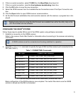
4. Connect the antenna cable to the antenna jack (J101) on the OEM615.
The antenna cable must have a right angle MCX connector on the end that connects to the OEM615.
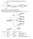
5. Align the OEM615 mating connector (J301) on the MIC with the 20-pin header (P1101) on the OEM615.
Make sure all of the pins on the header are aligned with the holes in the mating connector.
Press down on the MIC to seat the connector on the header.
6. Use the four screws supplied with MIC to secure the MIC to the OEM615.
7. Connect the IMU-to-MIC interface cable to the IMU.
8. Connect the IMU-to-MIC interface cable to the IMU connector on the MIC.
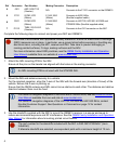
• Use the 10-pin locking connector (P701) for the ADIS IMU.
• Use the 20-pin locking connector (P601) for the HG1700, HG1900, HG1930 or STIM300 IMU.
9. Using a customer supplied wiring harness, connect a +10 to +30 V DC power supply to the power
connector (P101) on the MIC. This connection provides power to the MIC and the OEM615.
See the SPAN on OEM6 User Manual
for pin out information for the power connector.
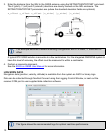
10. Using a customer supplied wiring harness, connect the communications connector (P301) to the user
system.
In a stack up configuration, the P301 connector provides connections for the: MIC serial port, OEM615
serial port (COM2), USB port, Event1 trigger, Event2 trigger, 1 Pulse Per Second (PPS) output,
Variable Frequency (VARF) output, Reset Input and Position Valid output.
See the SPAN on OEM6 User Manual
for pin out information for the communications connector.
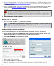
11. Skip to Install the PC Utilities on page 8.
Ensure all standoffs are properly installed and the mounting location for the receiver is level.
The amount of board deflection (bow and twist) must not exceed 0.75%. For example, on
the OEM615 which is 71 mm long and 46 mm wide, the deflection along the length must not
exceed 0.53 mm and the deflection along the width must not exceed 0.34 mm.
Do not apply power to the cards until the antenna cable is attached.
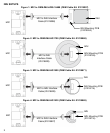
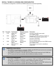
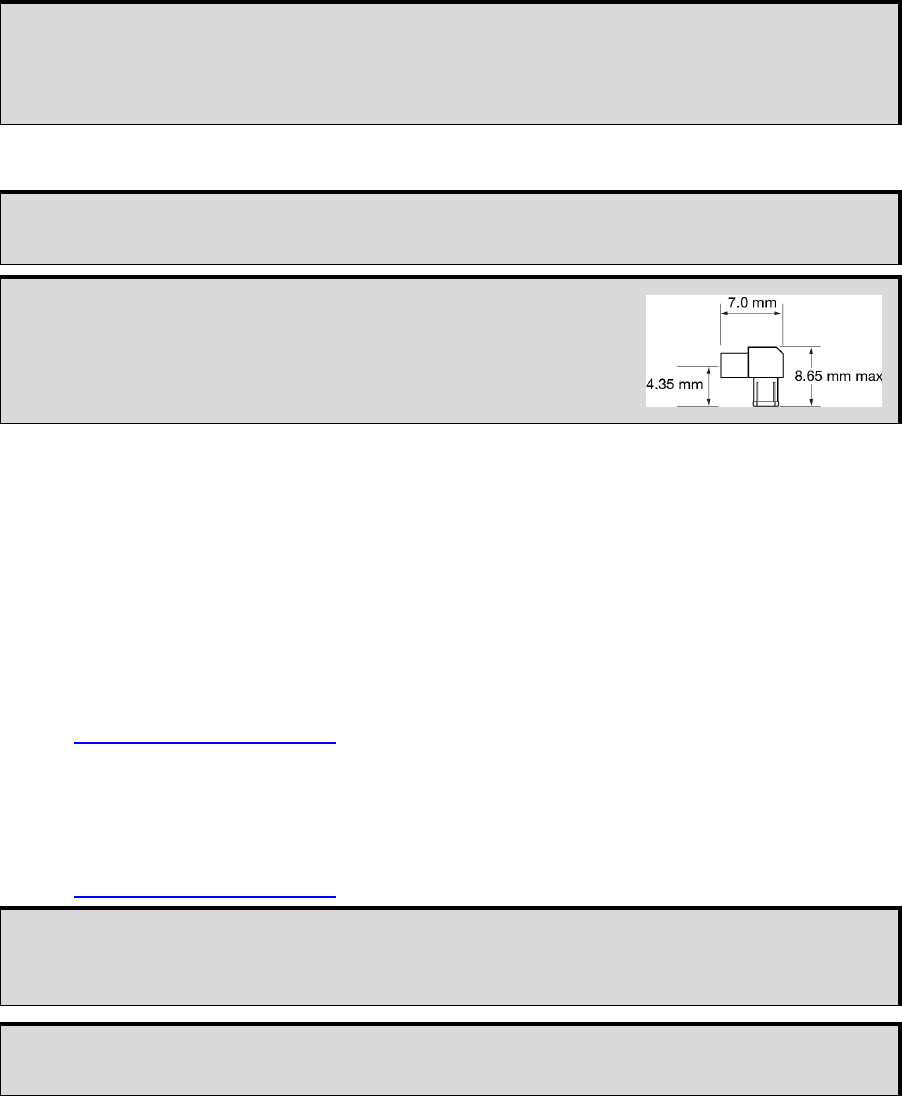
The part number for the recommended MCX connector is
M1051-110 (ShinA Telecom). If an alternate is used part, it
should meet the dimensions shown in the diagram.
The space between the OEM615 and the MIC is limited. The
height of the MCX connector must not exceed 8.65 mm.
All signal I/O with the exception of the USB port are at LVTTL levels.
To connect the MIC to devices that use other signals levels, such as a computer with an
RS-232 serial port, an interface circuit that converts to and from LVTTL must be used.
Use a twisted pair for the USB port connection and keep the wires as short as possible.