


6/28/2007 page 12 of 145
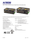
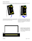
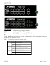
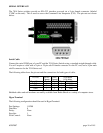
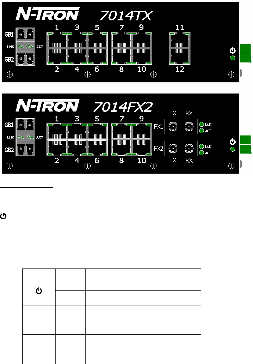
FRONT PANEL
From Top to Left:
Gigabit Ports 1000 Base SFP Fiber Transceivers (Optional)
RJ45 Ports Auto Sensing 10/100 Base-TX Connections
Fiber Ports 100 Base-FX Connections (only on 7014FX2 model)
Green LED lights when Power is supplied to the unit
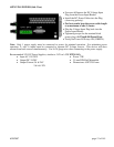
NOTE: The RJ45 data port has two LED’s located on each connector. The left LED indicates LINK status,
and the right LED indicates ACTIVITY.
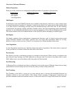
LED’s: The table below describes the operating modes:
LED Color Description
GREEN Power is Applied
OFF Power is OFF
GREEN 10/100/1000Mb Link between ports
LNK
OFF No Link between ports
GREEN Data is active between ports
ACT
OFF Data is inactive between ports