


44(86)
Cabling and connections
6
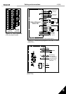
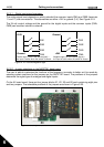
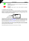
6.2.2.1 Digital input signal inversions
The active signal level depends on which potential the common inputs CMA and CMB (terminals
11 and 17) are connected to. The alternatives are either +24V or ground (0 V). See Figure 6-18.
The 24-volt control voltage and the ground for the digital inputs and the common inputs (CMA,
CMB) can be either internal or external.
Figure 6-18. Positive/Negative logic
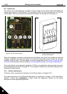
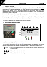
6.2.2.2 Jumper selections on the NXOPTA1 basic board
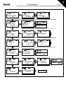
The user is able to customise the functions of the frequency converter to better suit his needs by
selecting certain positions for the jumpers on the NXOPTA1 board. The positions of the jumpers
determine the signal type of analogue and digital inputs.
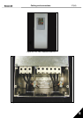
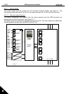
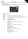
On the A1 basic board, there are four jumper blocks X1, X2, X3 and X6 each containing eight pins
and two jumpers. The selectable positions of the jumpers are shown in Figure 6-20.
Figure 6-19. Jumper blocks on NXOPTA1
+24V
+24V
DIN1
DIN2
DIN3
CMA
DIN1
DIN2
DIN3
CMA
Ground
Ground
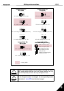
Positive logic (+24V is the active signal) =
the input is active when the switch is closed
Negative logic (0V is the active signal) =
the input is active when the switch is closed