


52(86)
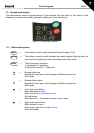
Control keypad
7
7.3.1
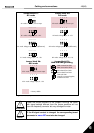
Monitoring menu (M1)
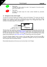
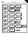
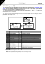
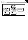
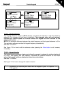
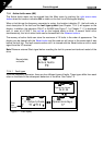
The monitoring menu can be entered from the main menu by pushing the Right arrow menu
button when the location indication
M1
is visible on the first line of the display. How to browse
through the monitored values is presented in Figure 7-4.
The monitored signals carry the indication
V#.#
and they are listed in Table 7-1. The values are
updated once every 0.3 seconds.
This menu is only for signal checking. The values cannot be altered here. For changing values of
parameters see Chapter 7.3.2.
Figure 7-4. Monitoring menu
Code Signal name Unit Description
V1.1
Output frequency Hz Frequency to the motor
V1.2
Frequency reference Hz
V1.3
Motor speed rpm Calculated motor speed
V1.4
Motor current A Measured motor current
V1.5
Motor torque % Calculated actual torque/nominal torque of the unit
V1.6
Motor power % Calculated actual power/nominal power of the unit
V1.7
Motor voltage V Calculated motor voltage
V1.8
DC-link voltage V Measured DC-link voltage
V1.9
Unit temperature ºC Heat sink temperature
V1.10
Voltage input V AI1
V1.11
Current input mA AI2
V1.12
DIN1, DIN2, DIN3 Digital input statuses
V1.13
DIN4, DIN5, DIN6 Digital input statuses
V1.14
DO1, RO1, RO2 Digital and relay output statuses
V1.15
Analogue output current mA AO1
Table 7-1. Monitored signals
Note:
Other applications may embody more monitoring values.
Monitor
V1
"
V14
READY
Local
Output frequency
13.95 Hz
READY
Local
FreqReference
13.95 Hz
READY
Lo ca l